Drive circuits for synchronous rectifiers

Inactive Publication Date: 2005-11-01
LAMBDA ELECTRONICS
View PDF13 Cites 111 Cited by
  • Summary
  • Abstract
  • Description
  • Claims
  • Application Information

AI Technical Summary

Benefits of technology

[0022]FIG. 4 is a schematic illustration of a circuit for generating a forward rectifier control signal, in accordance with an embodiment of the present invention;
[0023]FIG. 5 is a schematic illustration of a circuit for generating a freewheel (or flywheel) rectifier control signal,

Problems solved by technology

A problem associated with using transistors as synchronous rectifiers is the requirement for properly timed drive signals to control the switching of the synchronous rectifier transistors.
For example, improper timing of synchronous rectifiers in DC to DC converters may result in cross conduction through the rectifier at times other than the commutation interval, and/or in reverse recovery currents caused by the conduction of the body diode of one rectifier at the turn-on instant of the second rectifier.
In the case of a converter providing electrical isolation between its input and output, this problem is m

Method used


Image

  • Drive circuits for synchronous rectifiers
  • Drive circuits for synchronous rectifiers
  • Drive circuits for synchronous rectifiers

Examples


Embodiment Construction

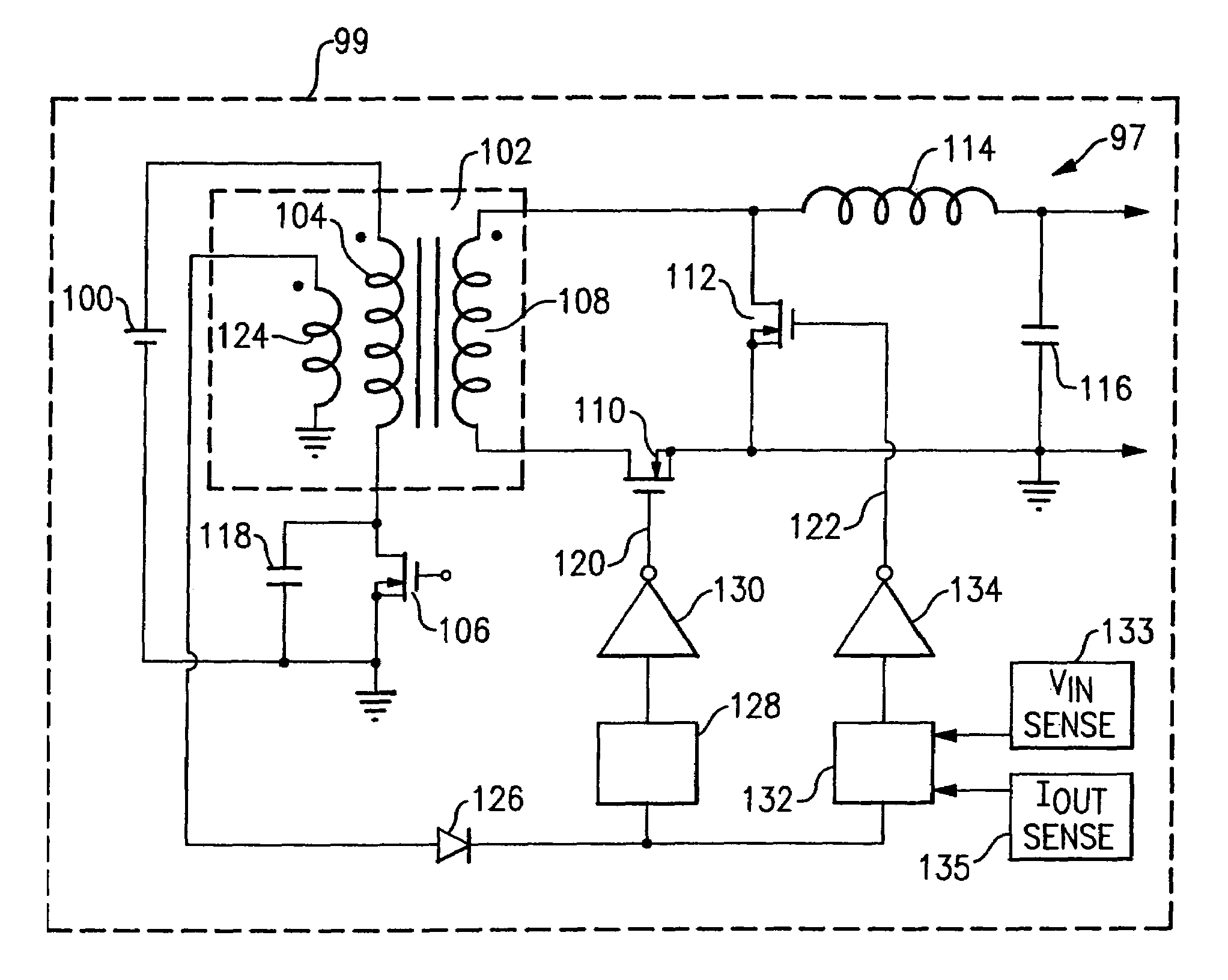
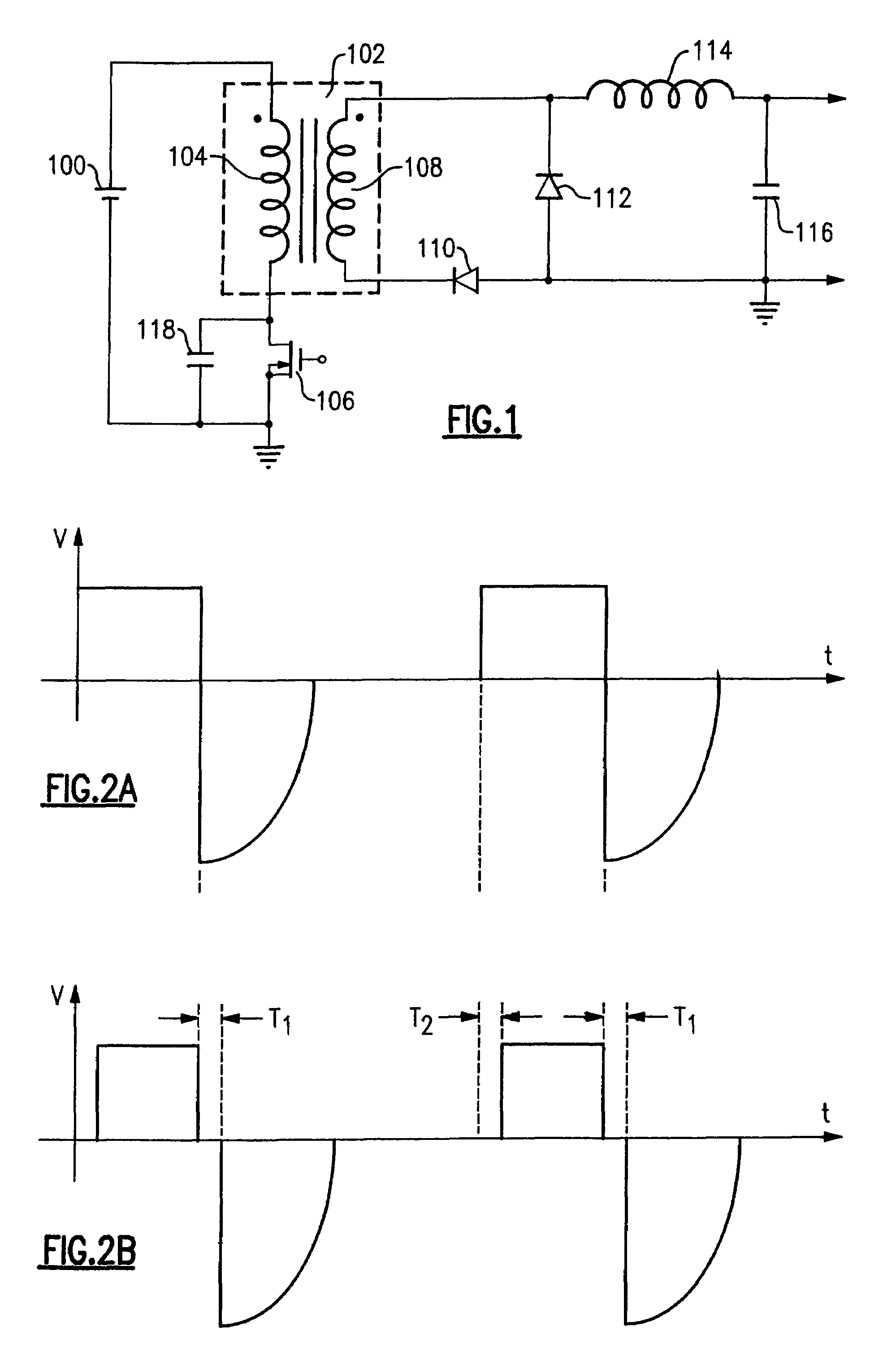
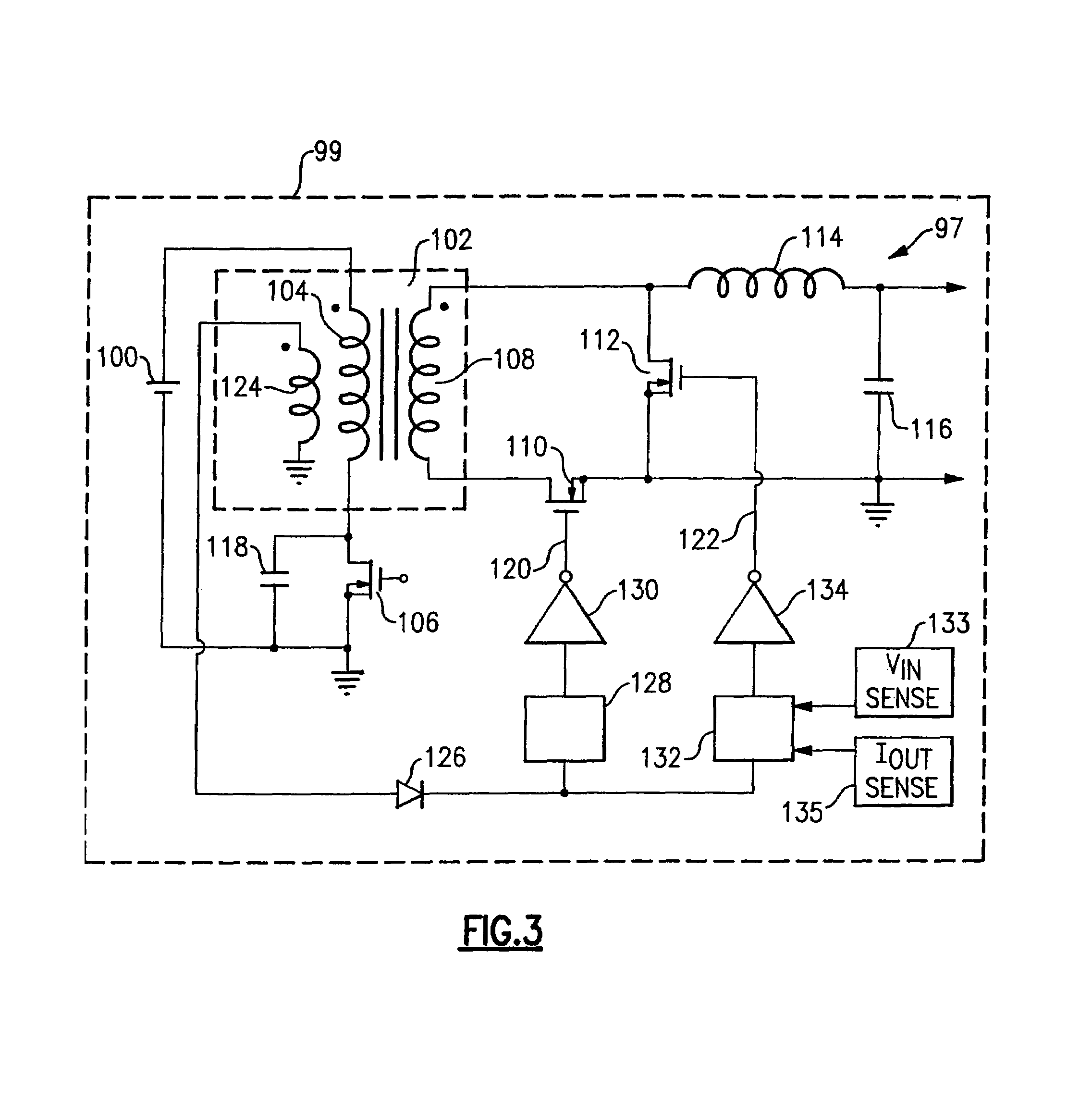
[0040]Prior to describing various illustrative embodiments of the invention, the present invention may be better appreciated with reference to FIG. 1, which schematically depicts a conventional resonant reset forward converter, which includes a transformer 102 having a primary winding 104 connected in series with a DC power source 100 (of voltage Vin) and a primary transistor 106, which has an associated parallel capacitance 118. Secondary winding 108 of transformer 102 is connected in series with a forward rectifier 110, and this series connection is connected in parallel with a freewheel rectifier 112. Forward rectifier 110 and freewheel rectifier 112 are situated to permit current flow to the converter output through filter inductor 114 at one end of filter capacitor 116. It may be appreciated that capacitance 118, sometimes referred to as a snubbing capacitance, schematically represents intrinsic capacitances (e.g., parasitic capacitances) as well as any extrinsic capacitances (...


PUM


Abstract

A method and system for providing synchronous rectification in power converters that includes controlling turnoff of a synchronous rectifier according to a timing signal representative of the switching time of a switch that is coupled to input of the power converter. Such a timing signal may be obtained directly or indirectly in various ways; for example, by sensing the voltage across the primary switch, or by sensing the drive voltage of the primary switch. Additional alternatives in an isolated converter having a transformer with a primary winding that is selectively coupled to the electrical power source includes sensing the primary winding voltage, for example, by directly sensing the primary voltage or by sensing the voltage across an auxiliary winding that is closely coupled to the primary winding.

Description

[0001]This application claims the benefit of U.S. Provisional Application No. 60 / 158,539, filed Oct. 8, 1999.FIELD OF THE INVENTION[0002]The present invention relates to synchronous rectification in switchmode converters, and more specifically, to generating drive signals for synchronous rectifiers that may be implemented in various DC-to-DC converter topologies.BACKGROUND OF THE INVENTION[0003]Conventional switchmode converters typically include passive rectifying devices, such as Schottky diodes, through which output or load current flows during operation. In order to reduce conduction losses and improve efficiency, however, a passive rectifying device may be replaced with an active switching device (e.g., a transistor), referred to as a synchronous rectifier. Such a synchronous rectifier may be periodically driven into conduction and non-conduction modes in synchronism with a periodic waveform.[0004]A problem associated with using transistors as synchronous rectifiers is the requ...

Claims


Application Information

Patent Timeline
IPC IPC(8): H02M3/335H02M3/24H02M1/08
CPCH02M1/08H02M3/33592Y02B70/1475Y02B70/10
Inventor COHEN, ISAAC
Owner LAMBDA ELECTRONICS
Why Eureka
Try Eureka