
Processor state reintegration using bridge direct memory access controller

Inactive Publication Date: 2005-11-01
ORACLE INT CORP
View PDF25 Cites 10 Cited by
  • Summary
  • Abstract
  • Description
  • Claims
  • Application Information

AI Technical Summary

Benefits of technology

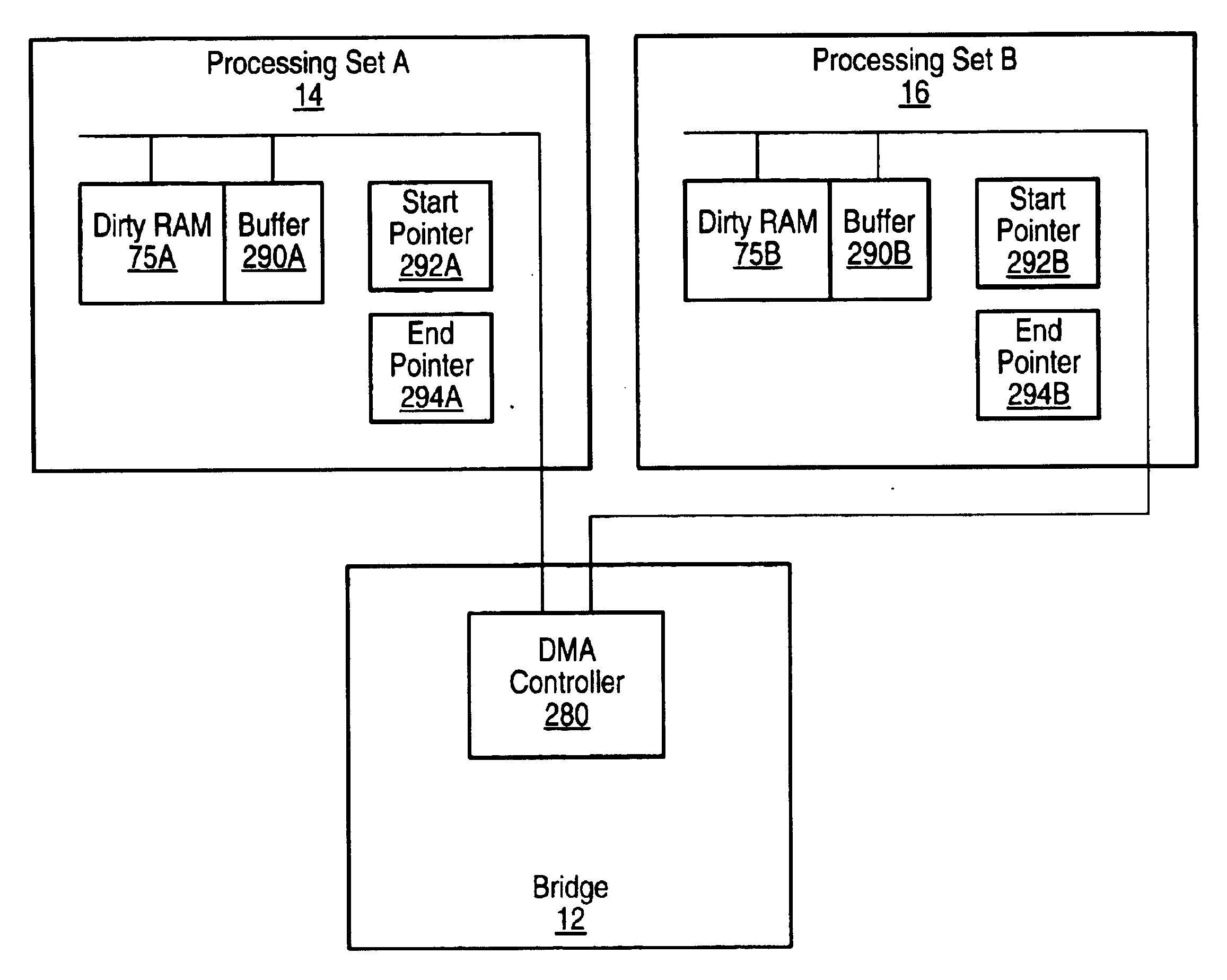
[0011]By using the direct memory access controller to copy dirtied blocks of memory from one processing set to another, the processor does not need to carry out the copying, whereby the processor overhead associated therewith can be avoided, increasing the efficiency of memory reintegration.
[0013]Preferably, however, the dirty memory comprises control logic operable to search the dirty memory for dirty indicators indicative of dirtied blocks. The control logic is operable to output references to the dirtied blocks of the main memory to be copied. Preferably the control logic is operable to buffer references to the dirtied blocks of the main memory to be copied. Providing the control logic with the dirty memory reduces unnecessary bus traffic.

Problems solved by technology

However, with a trend to increasing size of main memory and a desire to track dirtied areas of memory to a finer granularity (e.g. 1 KB) to minimise the amount of memory that needs to be copied, the size of the dirty RAM needed to track memory modifications is increasing.
With the increasing size of main memory and / or the reduced page sizes, the number of bits, and consequently the size of the dirty RAM that is needed to track memory changes can become large.
As a result of this, the time needed to search the dirty RAM to identify pages that may have been modified and will need to be re-copied, can increase to a point that it impacts on the time taken to re-integrate the main memory in the processing sets.
Another problem that can occur is increased risk of errors in the dirty RAM.

Method used


Image

  • Processor state reintegration using bridge direct memory access controller
  • Processor state reintegration using bridge direct memory access controller
  • Processor state reintegration using bridge direct memory access controller

Examples


Embodiment Construction

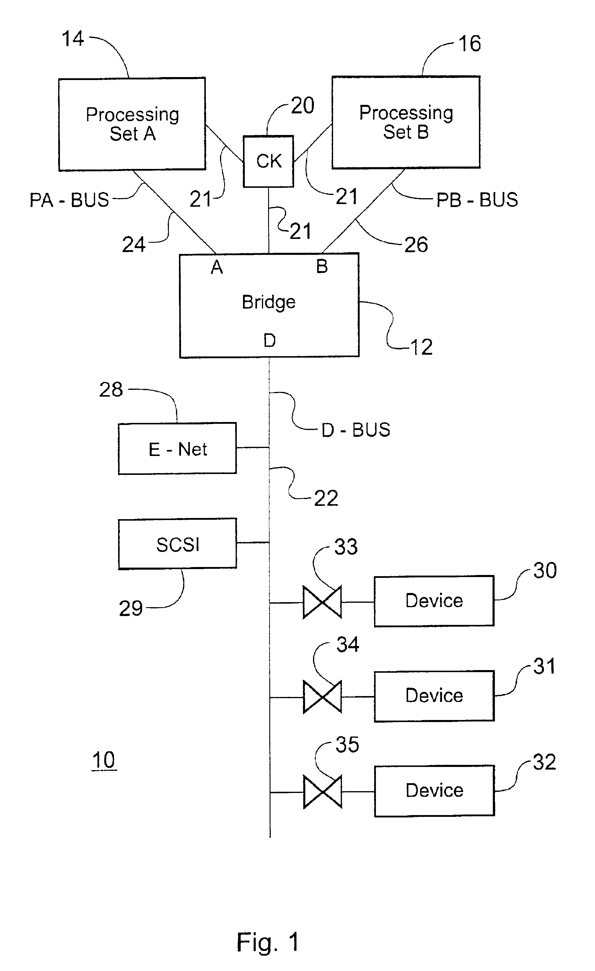
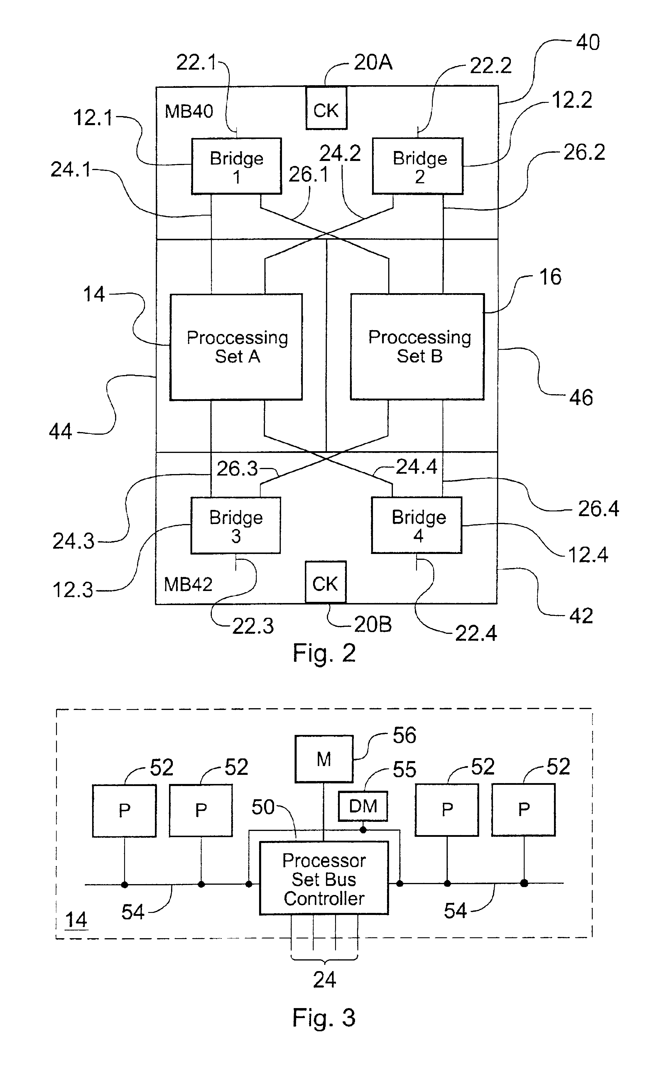
[0038]Exemplary embodiments of the present invention are described in the following with reference to the accompanying drawings. This embodiment is based on a fault tolerant computer system that includes multiple processing sets and a bridge of the type described in WO 99 / 66402, but modified to include a dirty memory (or dirty RAM) associated with each processing set. It will be appreciated from the following however, that this is merely an exemplary embodiment and that the invention is not limited to such an application.

[0039]FIG. 1 is a schematic overview of a fault tolerant computing system 10 comprising a plurality of CPUsets (processing sets) 14 and 16 and a bridge 12. As shown in FIG. 1, there are two processing sets 14 and 16, although in other examples there may be three or more processing sets. The bridge 12 forms an interface between the processing sets and I / O devices such as devices 28, 29, 30, 31 and 32. In this document, the term “processing set” is used to denote a gr...


PUM


Abstract

A computer system comprising at least two processing sets. Each processing set includes main memory. A bridge connects the processing sets. At least a first processing set further including a dirty memory having dirty indicators for indicating dirtied blocks of the main memory of the first processing set. The bridge includes a direct memory access controller that is operable to copy blocks of the first processing set indicated in the dirty memory to the main memory of another processing set. The processors do not, therefore, need to carry out the copying, whereby the processor overhead associated therewith can be avoided, increasing the efficiency of memory reintegration. The direct memory access controller can be arranged to search the dirty memory for dirty indicators indicative of dirtied blocks. Alternatively, the dirty memory can include control logic operable to search the dirty memory for dirty indicators indicative of dirtied blocks. The direct memory access controller can be arranged to instigate a search of the dirty memory.

Description

BACKGROUND OF THE INVENTION[0001]The invention relates to an apparatus and method for processor state reintegration.[0002]The invention finds particular, but not exclusive, application to fault tolerant computer systems such as lockstep fault tolerant computers which use multiple subsystems that run identically.[0003]In such lockstep fault tolerant computer systems, the outputs of the subsystems are compared within the computer and, if the outputs differ, some exceptional repair action is taken.[0004]U.S. Pat. No. 5,953,742 describes a fault tolerant computer system that includes a plurality of synchronous processing sets operating in lockstep. Each processing set comprises one or more processors and memory. The computer system includes a fault detector for detecting a fault event and for generating a fault signal. When a lockstep fault occurs, state is captured, diagnosis is carried out and the faulty processing set is identified and taken offline. When the processing set is replac...

Claims


Application Information

Patent Timeline
IPC IPC(8): G06F13/40
CPCG06F11/1658G06F13/4027
Inventor GARNETT, PAUL JEFFREYROWLINSON, STEPHENHARRIS, JEREMY GRAHAM
Owner ORACLE INT CORP
Learn More