Power drive mechanism for a motor vehicle liftgate having a disengageable gear train

a technology of power drive mechanism and gear train, which is applied in the direction of wing operation mechanism, door/window fitting, construction, etc., can solve the problems of excessive gear noise and gear slippag

Inactive Publication Date: 2005-11-08
ATOMA INT CORP +1
View PDF33 Cites 14 Cited by
  • Summary
  • Abstract
  • Description
  • Claims
  • Application Information

AI Technical Summary

Benefits of technology

[0006]The disadvantages of the prior art may be overcome by providing a power drive mechanism in which a gear train can be releasably locked or held in driving engagement during power assisted liftgate opening and closing and can be released from driving engagement thereafter to give the vehicle user the option of manually opening or closing the liftgate without backdriving the drive motor.
[0007]According to one aspect of the invention, there is provided a power drive mechanism for a driving a liftgate for a vehicle. The vehicle has a body controller controlling the operation of the power drive mechanism. The liftgate has a power operated latch assembly capable of primary and secondary latching engagement with a striker on the vehicle to releasably latch the liftgate and capable of power operated unlatching of the latching assembly. The power drive mechanism has a mounting bracket mountable on a “D” pillar of the vehicle. A linking arm is pivotally connected with the liftgate. A crank arm is pivotally mountable on the mounting bracket and pivotally connected with the linking arm. A gear train is pivotally mounted on said mounting bracket. A drive motor is mounted to the mounting bracket. The drive motor is operatively connected with the crank arm through the gear train. The gear train is movable between an engaged position and a disengaged position. The engaged position effects a driving engagement between the drive motor and the crank arm such that energizing the drive motor drivingly rotates the crank arm to responsively effect opening and closing of the liftgate. The disengaged position disengages the drive motor from the crank arm permitting movement of the crank arm without backdriving the drive motor. An actuator is operatively connected with the gear train and is operable to effect the movement of the gear train. A holding linkage is operatively connected between the gear train and the actuator to maintain the driving engagement once the actuator moves the gear train into the engaged position. A switch is mounted on the mounting bracket and is switchable in response to movement of the crank arm, indicating open and closed conditions of the liftgate. An electronic control unit electrically communicates with the body controller, the latch assembly, the drive motor, the switch and the actuator.

Problems solved by technology

This is undesirable because movement of the movable gear can result in gear slippage and / or in excessive gear noise.

Method used


Image

  • Power drive mechanism for a motor vehicle liftgate having a disengageable gear train
  • Power drive mechanism for a motor vehicle liftgate having a disengageable gear train
  • Power drive mechanism for a motor vehicle liftgate having a disengageable gear train

Examples


Embodiment Construction

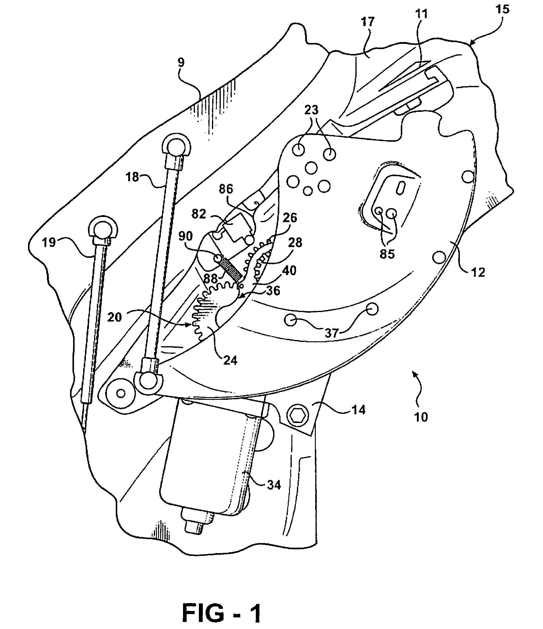
[0015]A power drive mechanism, generally designated 10, for power operated opening and closing of a vehicle liftgate 9 is shown in FIG.1. The structure of the vehicle liftgate 9 is conventional and is illustrated in U.S. Pat. Nos. 5,448,856 and 5,563,483. A typical vehicle liftgate 9 is pivotally mounted at the rear of a mini van or recreational-type vehicle by hinges (not shown) mounted between the top of the vehicle liftgate 9 and a portion 11 of the frame 15 of the vehicle. The liftgate 9 has a conventional power operated latch assembly (not shown) mounted at a central portion of its lower edge that releasably latches to a striker appropriately mounted on the vehicle frame.

[0016]When the latch assembly is released from the striker, the liftgate can be pivoted about the hinges from a lowered closed position to a raised open position to allow access to the vehicle interior through the rear of the vehicle. Typically, a gas strut of conventional construction is mounted between a resp...


PUM


Abstract

A power drive mechanism (10) for a motor vehicle liftgate includes a linking arm (18) pivotally connected with the liftgate, a crank arm (12) drivable for pivotal movement and connected with the linking arm (18), and a gear train (20) operatively engaging the crank arm (12). A drive motor (34) is operatively connected with the crank arm (12) through the gear train (20) to provide power assisted opening and closing of the liftgate. The gear train (20) is disengagable from the drive motor (34) to permit manual opening and closing of the liftgate without backdriving the drive motor (34). An actuator (74) is operatively connected with the gear train (20) to move the gear train into and out of engagement with the drive motor. A holding linkage (60, 62) is operatively associated with the gear train (20) to maintain the gear train (20) in engagement during power assisted opening and closing of the liftgate.

Description

[0001]This application is a continuation of U.S. patent application Ser. No. 09 / 959,222, filed Feb. 5, 2002, which is a 371 of PCT / CA00 / 00546, filed May 5, 2000, which claims benefit of U.S. Provisional Patent Application Ser. No. 60 / 132,701, filed May 5, 1999.FIELD OF THE INVENTION[0002]The invention relates to power drive mechanisms for power operation of a vehicle liftgate.BACKGROUND OF THE INVENTION[0003]Minivans and recreational vehicles frequently have rear liftgates that are pivotally mounted to the vehicle frame at the rear of the vehicle. The liftgate is pivotally mounted to the frame by top hinges to allow the liftgate to move between open and closed positions.[0004]Manually operated liftgates and power operated liftgates are well known. Power operated liftgates can be opened and closed manually if a vehicle user so desires. Power operated liftgates are typically driven in opening and closing directions by an electrical motor that is operatively engagable with the liftgate...

Claims


Application Information

Patent Timeline
Patent Type & Authority Patents(United States)
IPC IPC(8): E05F15/12
CPCE05F15/63E05F15/619E05Y2201/218E05Y2201/246E05Y2201/462E05Y2800/113E05Y2900/546E05Y2201/722
Inventor DANIELS, ANDREW R.OXLEY, PETER LANCEOLIVIER, ANDREGUSEV, VICTORFROMMER, THOMAS P.NOWICKI, WIESLAWBANIAK, GRZEGORZMOONEY, ROBERT B.BUTLER, FREDERICK C.
Owner ATOMA INT CORP
Why Eureka
Try Eureka