Hair dye applicator

a hair dye and applicator technology, applied in the direction of liquid transfer devices, functional valve types, flexible tubular containers, etc., can solve the problem that none of them, however, includes a removable dye container to provide a continuous supply of dye to a user's hair, and achieve the effect of avoiding spills and was

Inactive Publication Date: 2005-11-08
ANGUELO MICHAEL
View PDF12 Cites 33 Cited by
  • Summary
  • Abstract
  • Description
  • Claims
  • Application Information

AI Technical Summary

Benefits of technology

[0006]It is one of the main objects of the present invention to provide a hair dye applicat

Problems solved by technology

None of them, however, includes a removable dye containe

Method used


Image

  • Hair dye applicator
  • Hair dye applicator
  • Hair dye applicator

Examples


Embodiment Construction

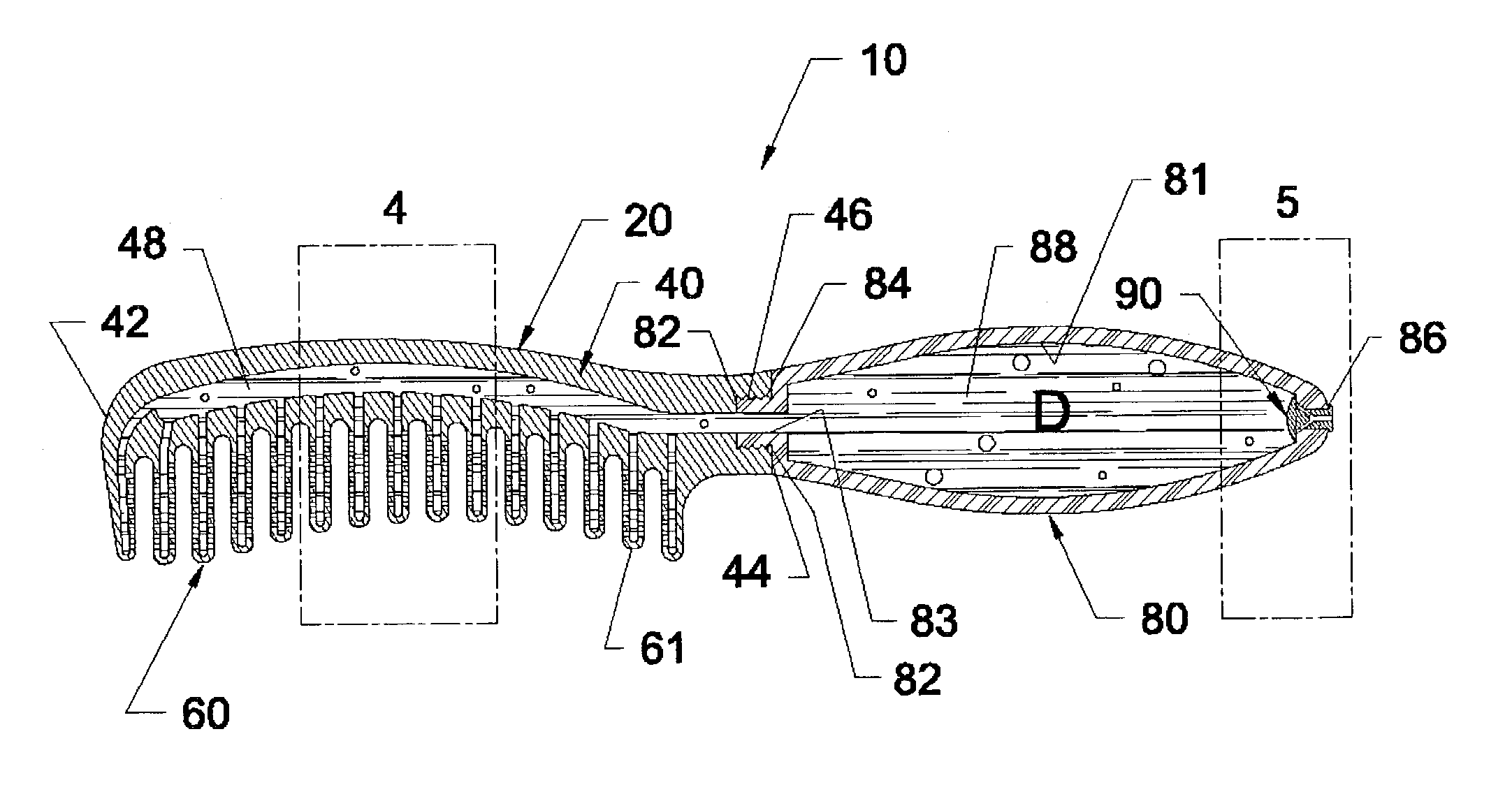
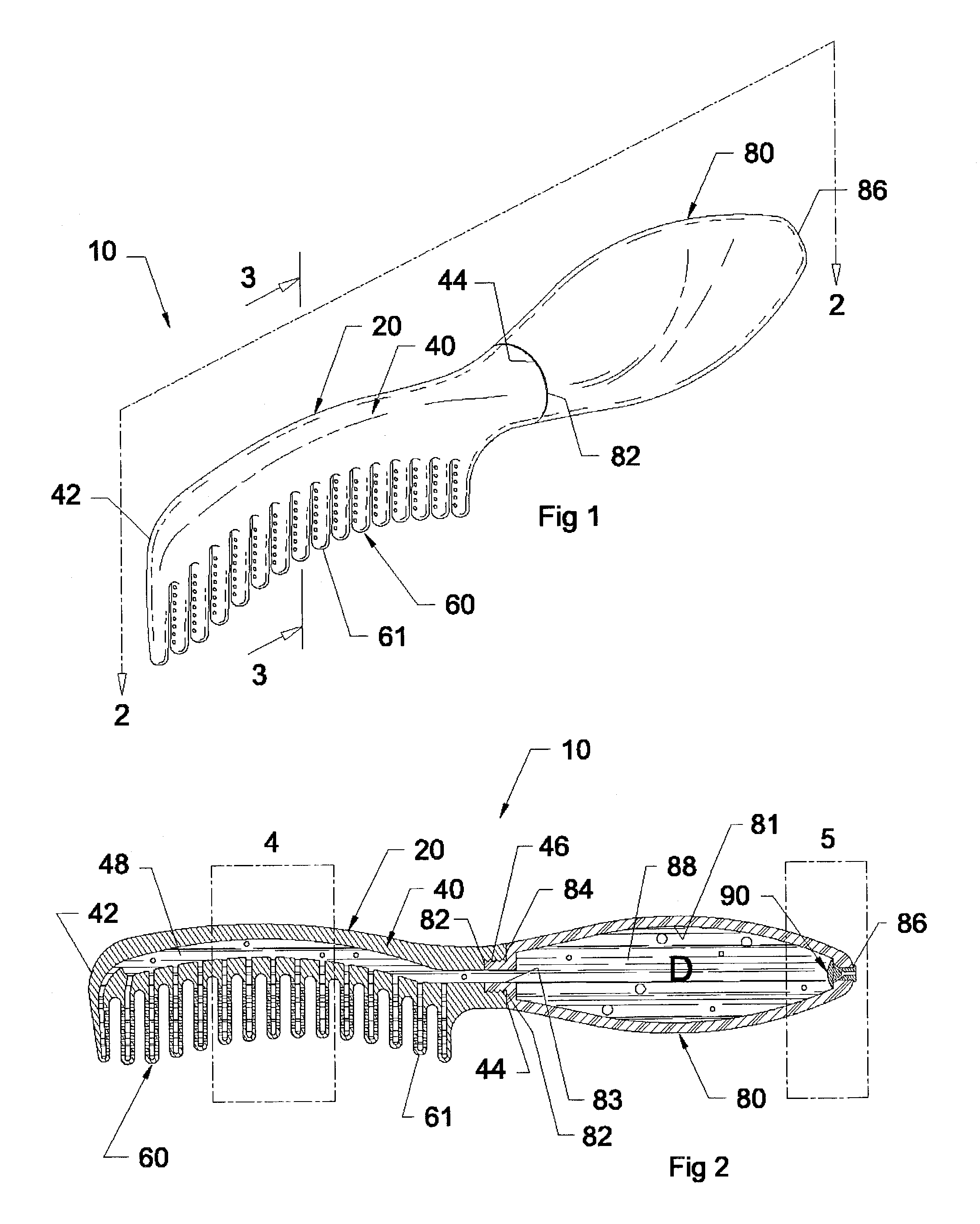
[0018]Referring now to the drawings, where the present invention is generally referred to with numeral 10, it can be observed that it basically includes comb assembly 20 and dye container assembly 80, as seen in FIG. 1. The latter doubles as the handle for applicator 10. Comb assembly 20 is preferably made out of a moldable plastic material. In production, it is envisioned that two symmetrical halves are molded and mounted together. Thus, the present invention also lends itself to be mass-produced.

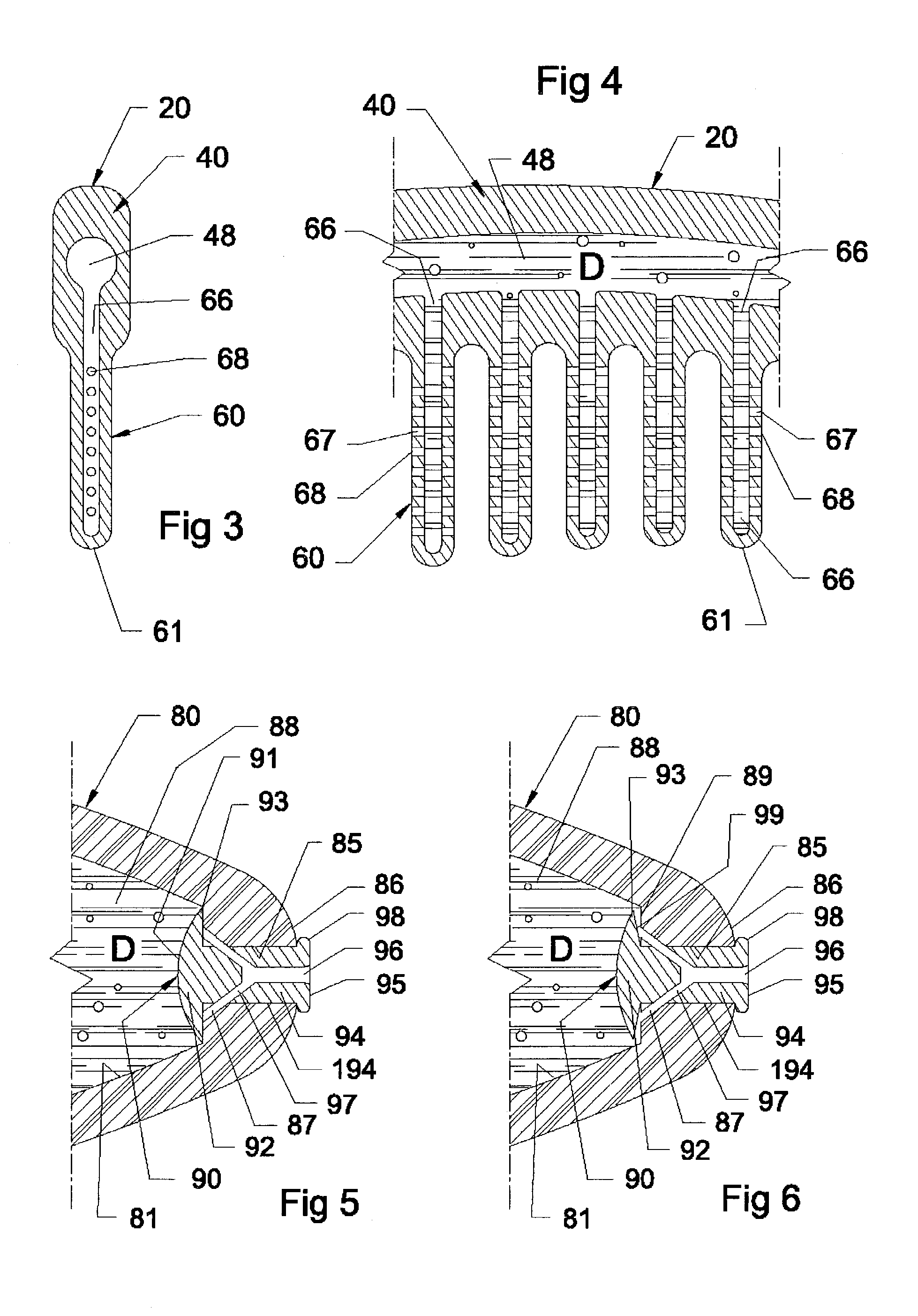
[0019]Comb assembly 20 includes longitudinally extending spine member 40 and a plurality of teeth 60. Spine member 40 includes front end 42, rear end 44 and longitudinally extending cavity 48, as best seen in FIG. 2. Rear end 44 includes threaded through opening 46 that matingly receives dye container assembly 80. Internal longitudinal cavity 48 extends along spine 40 from opening 46 at rear end 44 towards end 42, without reaching the latter. Teeth 60 are perpendicularly mounted to spine m...


PUM


Abstract

A dye applicator that has an elongated container that doubles as a handle and a comb assembly with an internal longitudinal cavity along its spine. The container is removably connected to the comb assembly to permit the dye to pass through the cavity and to the longitudinal and transversal opening in each tooth. The dye goes out to the user's hair through opening terminations on each of the transversal conduits. The container assembly is deformable to squeeze out the dye and a one-way valve is used to permit the air to replace the dye that is released.

Description

BACKGROUND OF THE INVENTION[0001]1. Field of the Invention[0002]The present invention relates to a hair dye applicator, and more particularly, to such a device that includes a removable and refillable container for the dye that doubles as a handle.[0003]2. Description of the Related Art[0004]Several dye applicators have been developed in the past. None of them, however, includes a removable dye container to provide a continuous supply of dye to a user's hair. The hair dye applicator includes a number of parallel teeth with internal longitudinal and transversal cavities to deliver the dye through several openings cooperative disposed in the opposite sides of the teeth.[0005]Applicant believes that the closest reference corresponds to U.S. Pat. No. 5,975,089 issued to Joseph T. Simon in Nov. 2, 1999 for a hair brush applicator. Simon's patented hairbrush applicator includes a hairbrush with a handle portion and a head portion. The handle portion has a chamber therein and the head port...

Claims


Application Information

Patent Timeline
IPC IPC(8): A45D24/22A45D24/00B65D35/18B65D35/00
CPCA45D24/22Y10T137/789
Inventor ANGUELO, MICHAEL
Owner ANGUELO MICHAEL
Why Eureka
Try Eureka