Hydraulic fluid reservoir and hydraulic system

Inactive Publication Date: 2005-11-08
TELEFLEX CANADA
View PDF7 Cites 11 Cited by
  • Summary
  • Abstract
  • Description
  • Claims
  • Application Information

AI Technical Summary

Benefits of technology

[0005]It is another object of the invention to provide an improved hydraulic fluid res

Problems solved by technology

One problem associated with such systems is ensuring that a proper level of fluid is maintained in the reservoir.
However, in practice air frequently becomes entrained in the fluid and causes the color of the fluid to lighten.
This may confuse the sensor and may lead to incorrect readings on the level of the fluid within the reservoir.
Another problem associated with hydraulic reservoirs is the necessity in some systems to accommodate differential flows of fluids flowing

Method used


Image

  • Hydraulic fluid reservoir and hydraulic system
  • Hydraulic fluid reservoir and hydraulic system
  • Hydraulic fluid reservoir and hydraulic system

Examples


Embodiment Construction

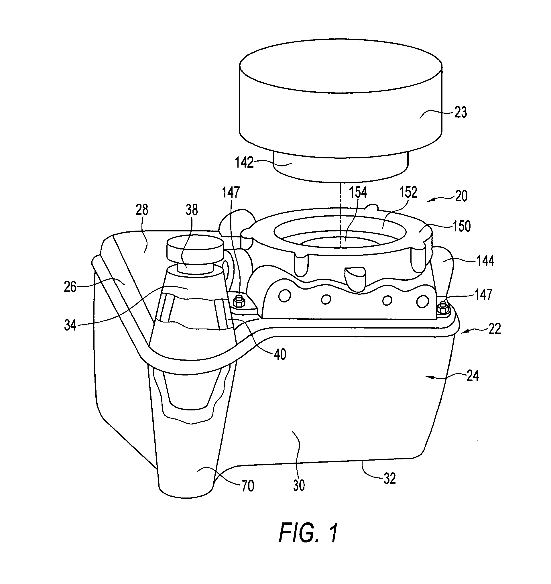
[0024]Referring to the drawings, and first to FIG. 1, the shows a combination 20 of a hydraulic fluid reservoir 22 and a hydraulic fluid pump 23. The reservoir 22 includes a container 24 having a top portion 26 with a top 28 and a bottom portion 30 with a bottom 32. The container in this example is of polyethylene although polypropylene, other plastics or other materials could be substituted.

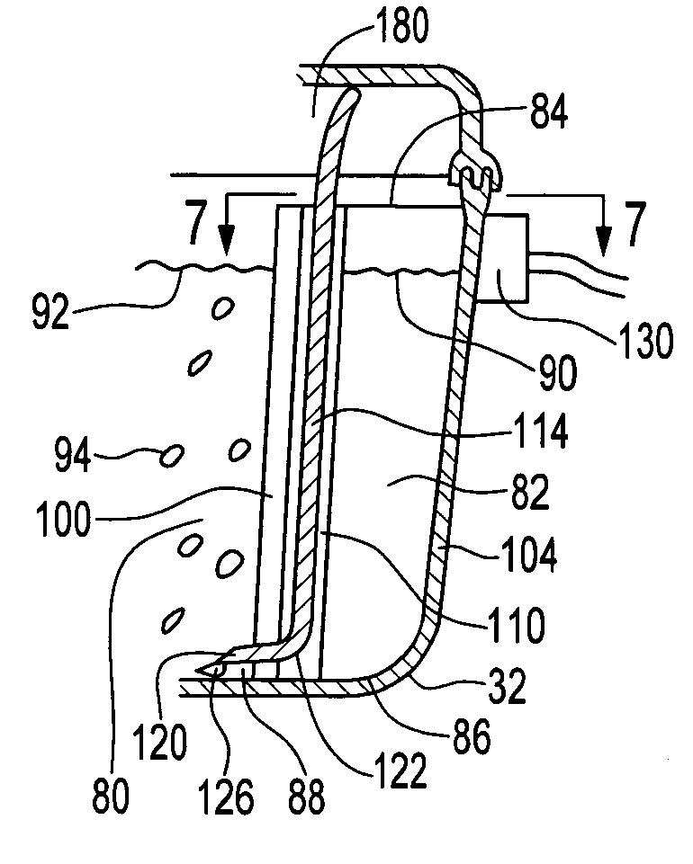
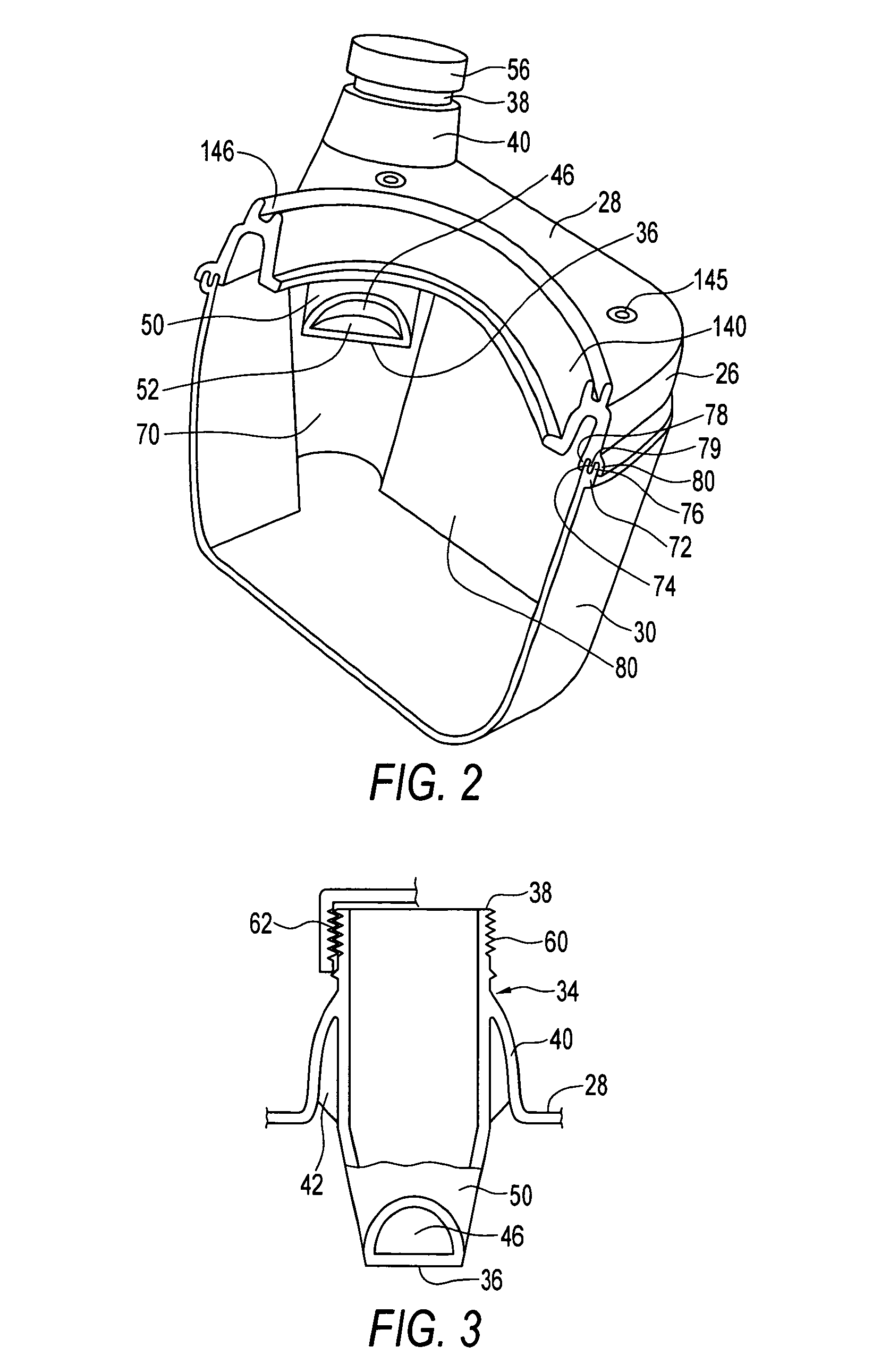
[0025]The reservoir includes a filler conduit 34 which has a bottom 36 within the container as seen in FIG. 2. The conduit has a top 38 which is above the bottom of the conduit. As seen best in FIGS. 2 and 3, the conduit is tubular and tapers towards the bottom in this example although this is not critical. The conduit is integral with top portion 26 of the container in this example and is connected to an upwardly extending, annular part 40 of the top portion of the container as seen best in FIGS. 2 and 3. A series of spaced-apart flanges 42 extend between the annular part 40 of the top and the ...


PUM

PropertyMeasurementUnit
Levelaaaaaaaaaa

Abstract

A hydraulic fluid reservoir and hydraulic pump combination has at least one hydraulic fluid port and includes a container with a hollow body having a top and a conduit having a bottom within the container and a top above the bottom. The conduit has an opening adjacent to the bottom of the conduit. The opening is spaced apart below the top of the container. A closure member is releasably, sealingly connected to the top of the conduit. Hydraulic fluid can be added to the container via the conduit up to the level of the opening of the conduit. Addition of further hydraulic fluid fills the conduit to the top thereof and the conduit overflows if additional hydraulic fluid is added after the top of the conduit is reached by the fluid. Preferably the container has a main interior chamber and a smaller chamber which is adjacent to one of the side walls of the container. The smaller chamber is has a bottom opening near the bottom of the smaller chamber which communicates with the main interior chamber. Hydraulic fluid enters the smaller chamber through the opening and reaches the level of hydraulic fluid in the main interior chamber. Bubbles in the hydraulic fluid within the main interior chamber are isolated from the smaller chamber and accordingly do not impair the reading of the hydraulic fluid level by a photo detector.

Description

BACKGROUND OF THE INVENTION[0001]This invention relates to hydraulic fluid systems and, in particular, to hydraulic fluid reservoirs having photodetectors for sensing fluid level and to reservoirs for use with unbalanced hydraulic cylinders.[0002]Hydraulic reservoirs are common components for many hydraulic systems, for example for use in providing pressurized hydraulic fluid to hydraulic cylinders. One problem associated with such systems is ensuring that a proper level of fluid is maintained in the reservoir. One solution to this problem has been placing a photodetector in a position to detect the level of fluid in the reservoir through a transparent or translucent portion of the reservoir. The fluid is colored and this coloration assists the sensor in detecting the presence or absence of fluid within the container and accordingly the level of fluid. However, in practice air frequently becomes entrained in the fluid and causes the color of the fluid to lighten. This may confuse th...

Claims


Application Information

Patent Timeline
IPC IPC(8): F15B1/26F15B1/00F04B23/00F04B23/02
CPCB60T11/22B60T11/26B60T17/06F04B23/025F15B1/26Y10T137/86212Y10T137/86035Y10T137/86372Y10T137/8342
Inventor DUDRA, BRIAN
Owner TELEFLEX CANADA
Why Eureka
Try Eureka