Flywheel-driven vehicle

a technology of flying wheel and vehicle, which is applied in the direction of electric propulsion mounting, battery/fuel cell control arrangement, battery/cell propulsion, etc., can solve the problems of dwindling fuel supply and difficulty in actual execution of the concep

Inactive Publication Date: 2005-11-08
BERBARI GEORGE EDMOND MR
View PDF34 Cites 52 Cited by
  • Summary
  • Abstract
  • Description
  • Claims
  • Application Information

AI Technical Summary

Benefits of technology

[0005]Accordingly, it is an object of the present invention to solve the foregoing problems and shortcomings in the prior art. In the present invention, a flywheel-driven system has two or more batteries (or sets of batteries) that alternately power the electr

Problems solved by technology

This urgency is constantly reenforced by higher fuel prices, dwindling fuel supplies, and reports of dire environmental effects of internal combustion engine exhaust.
The dif

Method used


Image

  • Flywheel-driven vehicle
  • Flywheel-driven vehicle
  • Flywheel-driven vehicle

Examples


Embodiment Construction

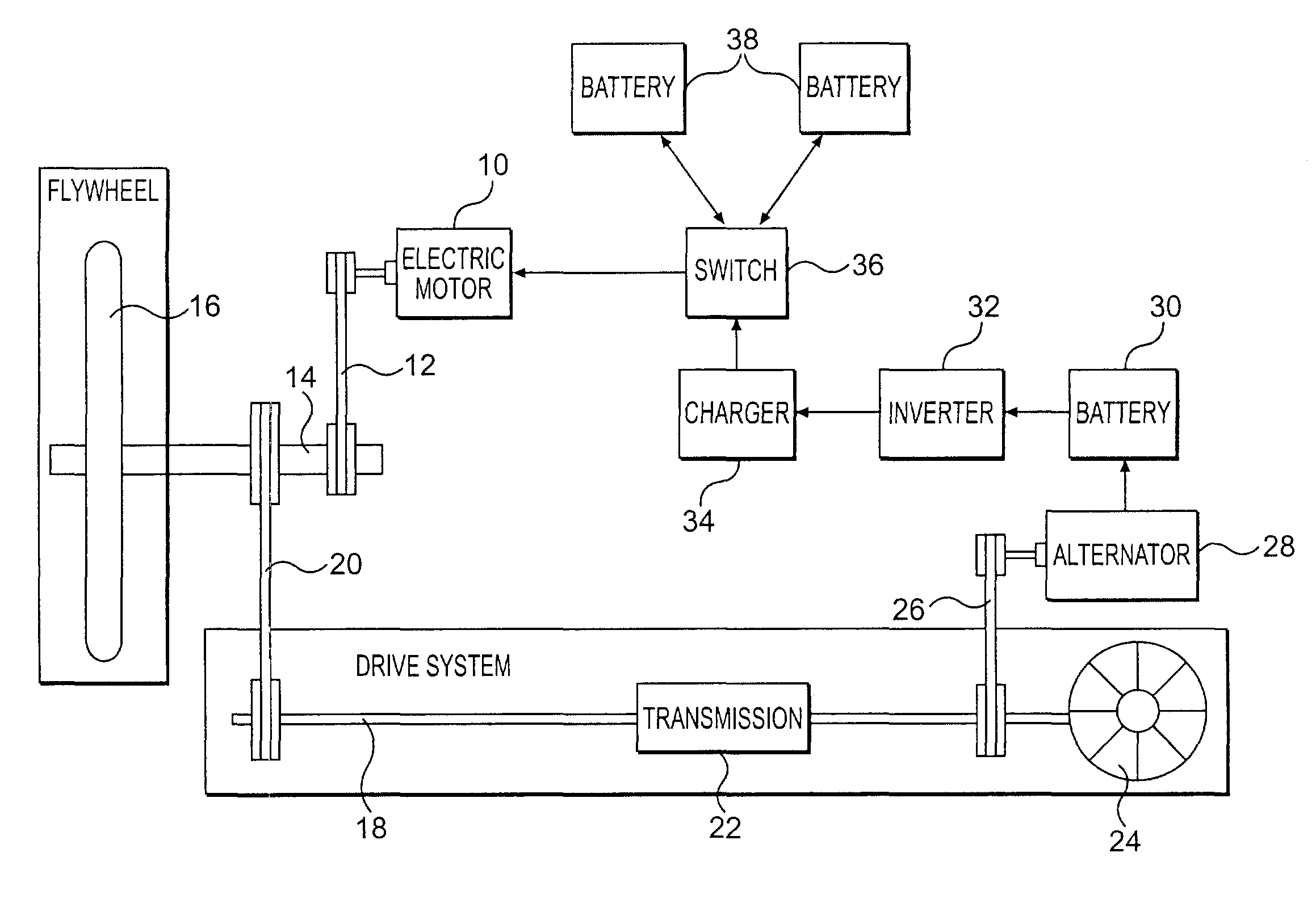
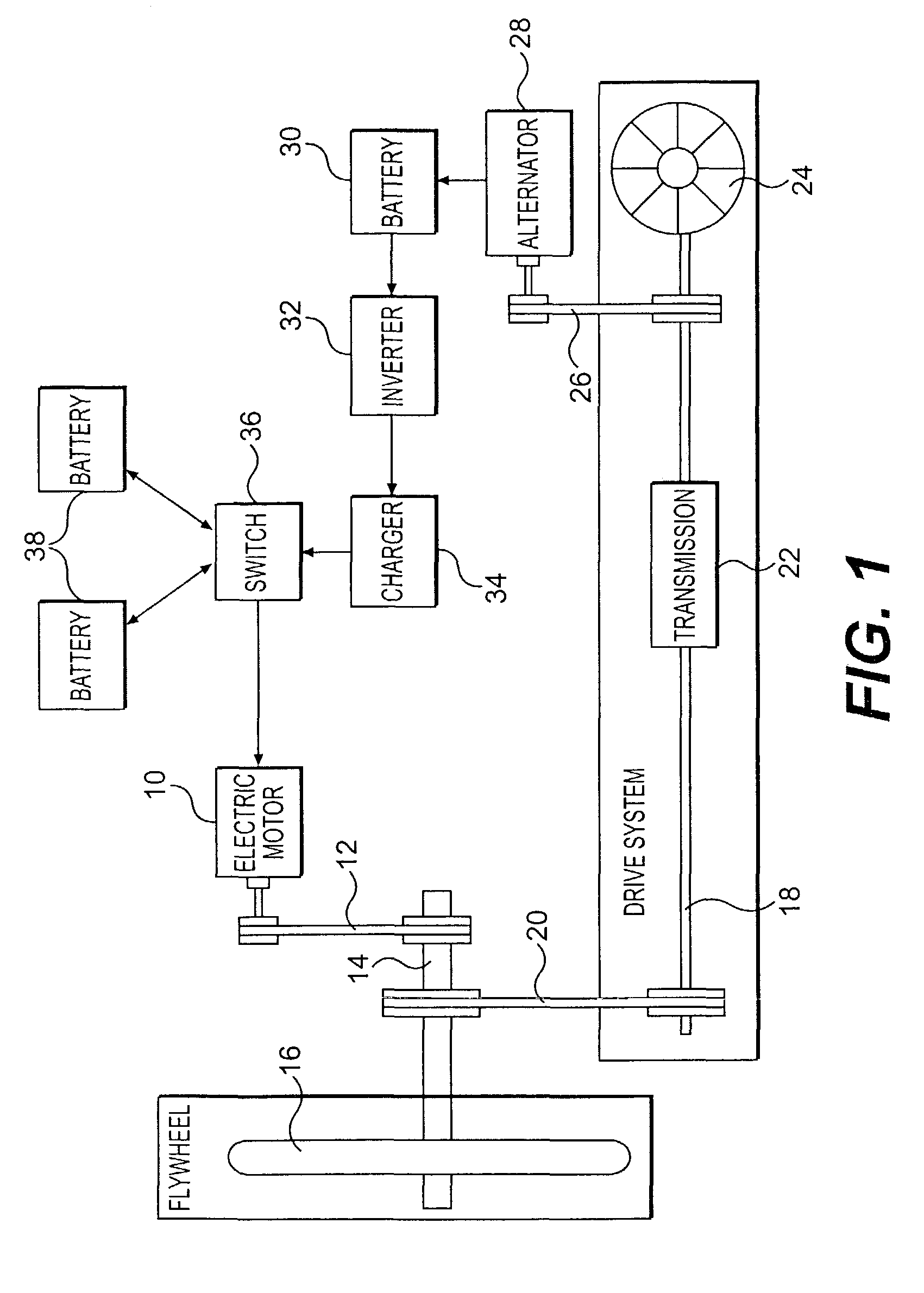
[0012]The present invention is directed to the specific field of flywheel-driven vehicles. That is, a flywheel is linked to and is the energy source for the rotation of the drive system. (drive shaft) of a vehicle. The rotation of the flywheel is initiated and maintained by an electric motor, wherein the electric motor is powered alternatively by a plurality of batteries (or sets of batteries). A charger assembly is also connected to the plurality of batteries. In operation, one battery at a time powers the electric motor while, simultaneously, the other battery(s) is / are being recharged. A switch operates to deliver electricity to the electric motor from alternative batteries, while making sure that the flow of recharge energy is directed to each battery that is not powering the electric motor at that time.

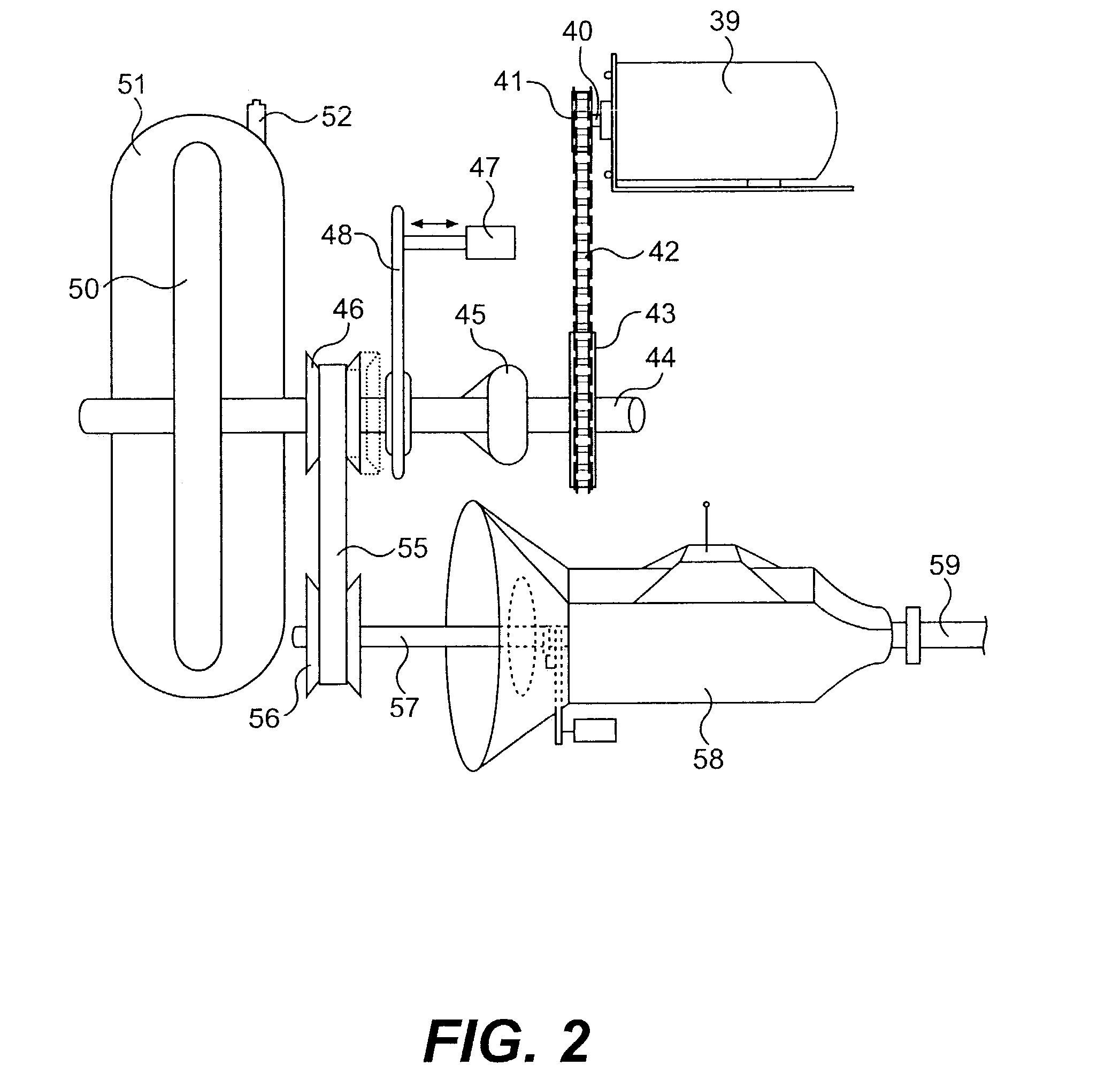
[0013]The following description is generally in the context of a working prototype of the claimed invention. Inevitably, there will be refinements and variations made on the pres...


PUM


Abstract

A flywheel-driven vehicle is powered by an electric motor. The rotation of the flywheel is initiated and maintained by an electric motor, wherein the electric motor is powered alternatively by a plurality of batteries (or sets of batteries). A charger assembly is connected to the plurality of batteries. In operation, one battery at a time powers the electric motor while, simultaneously, the other battery(s) is/are being recharged.

Description

[0001]This invention relates to a vehicle powered by a flywheel. Specifically, it relates to a drive system for a vehicle having an electric motor that causes rotation of a flywheel, and the energy then stored in the flywheel is used to drive the vehicle.BACKGROUND OF THE INVENTION[0002]The need for energy efficient and clean-running vehicles has existed for many years. This urgency is constantly reenforced by higher fuel prices, dwindling fuel supplies, and reports of dire environmental effects of internal combustion engine exhaust. Much of the popular effort directed to solving these problems includes increasing the efficiency of internal combustion engines thereby resulting in cars with greater gas mileage.[0003]One area of effort in seeking fuel efficient vehicles is in the hybrid type of cars. Generically speaking, these cars combine gas and electric motors. Those motors compliment each other to obtain efficiencies. In some of these types of cars, small flywheels are used to re...

Claims


Application Information

Patent Timeline
IPC IPC(8): B60K6/00B60K6/10B60K6/30B60K6/46B60L50/30
CPCB60K6/105B60L11/126B60L11/16B60L11/1853B60L11/1864B60K6/46Y02T10/7027B60L2210/40Y02T10/6204Y02T10/6217Y02T10/7005Y02T10/7033Y02T10/7061Y02T10/7077Y02T10/7241B60L50/62B60L50/30B60L58/18B60L58/21Y02T10/62Y02T10/70Y02T10/72Y02T10/7072
Inventor BERBARI, GEORGE EDMOND
Owner BERBARI GEORGE EDMOND MR
Why Eureka
Try Eureka