Depth and width adjustable display track unit with removable partitions

a technology of display track and partition, which is applied in the field of display track, can solve the problems of not being readily accessible to a potential customer, not being easily hidden from the customer view, and not being easily accessible to counters, tabletops or refrigeration trays. small, easy to los

Inactive Publication Date: 2005-11-08
MARMON FOODSERVICE TECH INC
View PDF32 Cites 117 Cited by
  • Summary
  • Abstract
  • Description
  • Claims
  • Application Information

AI Technical Summary

Benefits of technology

[0028]This basement comprises structure and space to receive positioning and releasable locking tabs or fingers that extend from the partitions downward between pairs of adjacent ribs and engage basement structure below the ceiling. In some embodiments, the downward extending fingers from the partitions engage the bottom surfaces of transverse beams; in other embodiments these fingers engage the bottom surfaces of the longitudinal ribs. In all these embodiments the fingers cooperate with the basement structure to help position, stabilize and secure the partitions with respect to the display tracks, and particularly to prevent partitions from being lifted or otherwise unintentionally displaced from their proper position. The basement further provides structure to engage the various coupling elements for joining display track segments to extend in the longitudinal and / or transverse direction.
[0029]It is a further object of this invention to provide on the bottom of each partition a plurality and darts or arrow shaped coupling means which extend downward between adjacent longitudinal ribs in the display track for releasably coupling thereto. In a preferred embodiment these downward extending coupling means extending alternatively left and right and are resilient for easier installation and removal.
[0031]A further object of this invention is to provide additional support and strengthening means for the plurality of display tracks which are coupled together in a transverse direction. This strengthening is provided by a transverse beam extending across and snugly engaging the front walls of all of the display track segments that are joined together side-by-side. A variation of this beam not only traverses and engages all the front walls of the joined display track units, but extends upward and is called lip extender to serve the additional function of stopping articles from falling off the front.
[0033]A still further object of this invention to arrange for the partition to be stabilized in its desired location by having a plurality of longitudinally spaced fingers each extending forward so that the partition, when installed and slid forward, cannot be displaced upward by accident unless and until the user releases the coupling and pushes the partition rearward to disengage the forward directed fingers. Here a trigger release will allow the partition to be slid rearward and then lifted upward.
[0035]A further object of this invention it to configure the longitudinal ribs to have triangular cross-section where the apex of the triangle faces upward and where the adjacent sides of adjacent ribs define a generally triangular space pointing downward. The bottom portion of the partition has a downward pointing triangular shape whose sides engage the spaced apart sloping sides of the two triangular ribs. The ribs thus support the partition from extending farther downward and also stabilize it from tilting or rocking while it is coupled to these longitudinal ribs. Coupling is enhanced by a tooth surface or tab which is cammed transversely as the partition is pressed downward, until it snaps under one of the longitudinal ribs. It is subsequently releasable by tilting and pulling of the partition upward.

Problems solved by technology

If the display shelf does not occupy the full depth, objects placed on the support surface in front of the display shelf will conceal the products intended to be displayed on the display shelf, while objects placed on the support surface behind the display shelf will be at least partially hidden from customer view and not readily accessible to a potential customer.
An obvious disadvantage of this solution to the problem is that some counters, tabletops or refrigeration trays will be deeper than the “standard depth” display shelves.
Such connecters are typically relatively small and easy to lose during the assembly process.
The add-on sections solution further entails logistical problems in that a separate inventory of the add-on sections must be maintained by the manufacturer, made available for purchase, and delivered to purchasers.
As a practical matter, the dilemma of the producer is even greater since the customer may desire add-on sections of different depths so that the customer can make full use of the available depths of a variety of different-depth support surfaces.
Further problems with partitions are that products divided by the partitions nevertheless tend to topple off the front of the display track or in display cabinets with front doors, to slide too far and lie against the front door and then fall out when the door is open.
Also these partitions become dislodged because customers pull on products or pull on the partitions themselves when products become wedged between them.
Typical prior art partitions have included numerous structural and functional features which inhibit their usefulness.
For example, ease of installation and removal often results in partitions that are easily dislodged or are unstable against topping forces.
Conversely, highly secure and stable partitions are often quite cumbersome to install and remove.
Efforts to solve these problems have been hindered by various factors inherent in the industry, including the need to maximize display space, and to incorporate maximum flexibility to enlarge or reduce display rack dimensions, and to render these products so user friendly that minimum training is required for installation and adjustment.

Method used


Image

  • Depth and width adjustable display track unit with removable partitions
  • Depth and width adjustable display track unit with removable partitions
  • Depth and width adjustable display track unit with removable partitions

Examples


Embodiment Construction

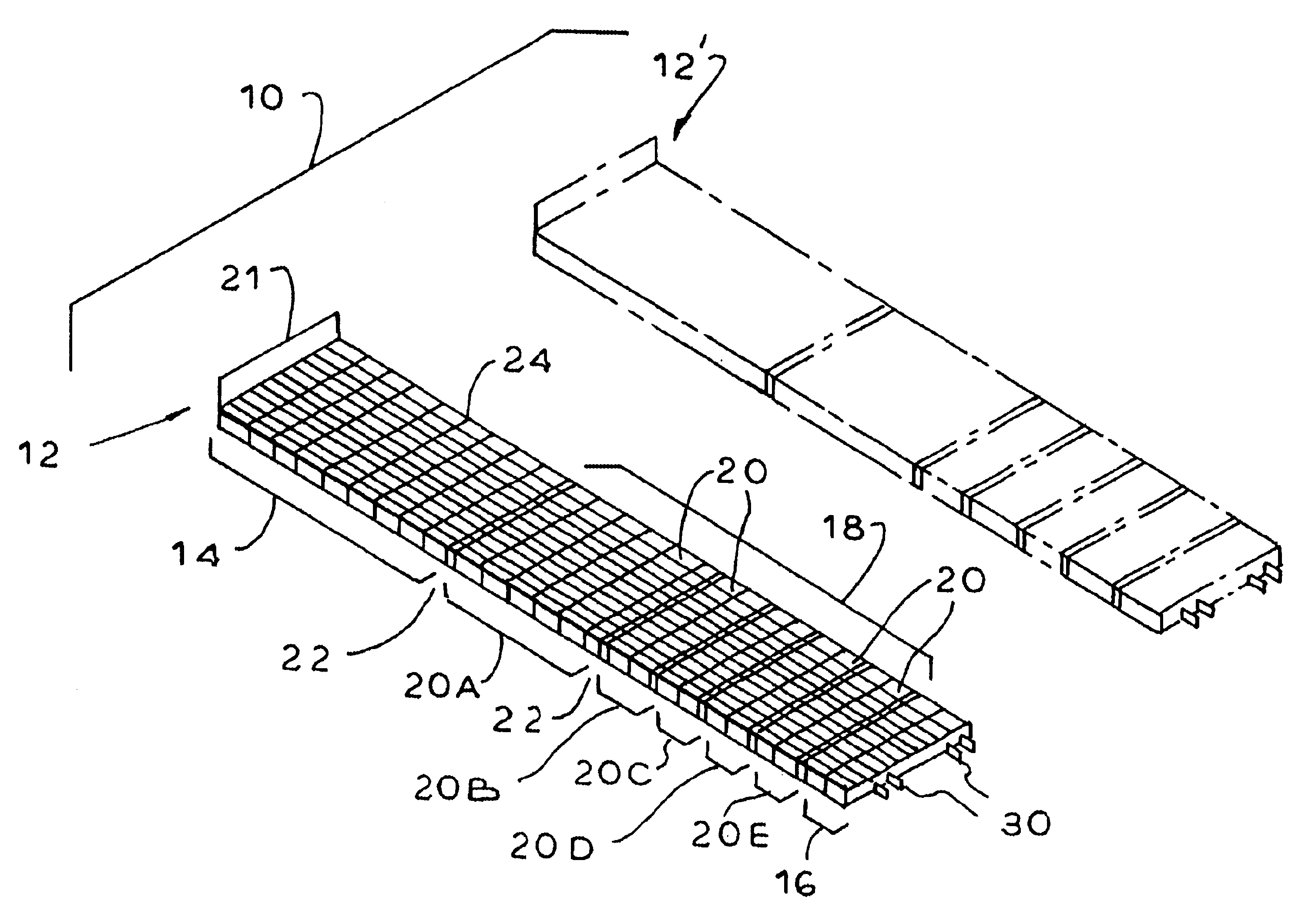
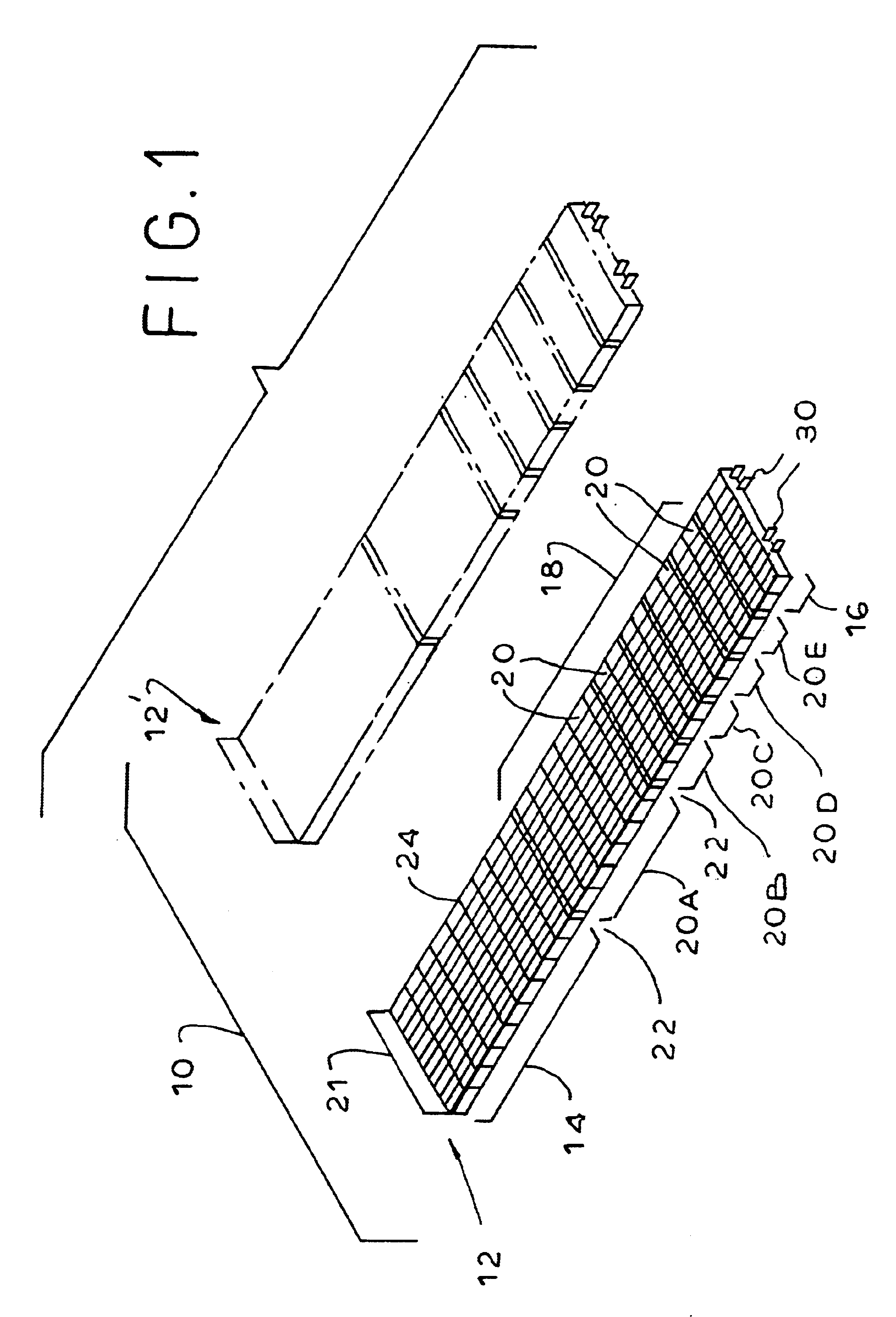
[0068]While the present invention will be illustrated and described herein in the context of a display shelf consisting of a single display track, it will be apparent to those skilled in the art that the same principles may be applied to any display shelf, whether it contains only one or a plurality of display tracks.

[0069]Referring now to the drawing, and in particular FIG. 1 thereof, therein illustrated is a depth-extendable display track unit according to the present invention, generally designated by the reference numeral 10. The unit 10 consists of at least two essentially identical standard depth display tracks, generally designated 12, 12′. The display tracks 12, 12′ are essentially identical in that they are formed in essentially identical molds and preferably have essentially identical surface ornamentation applied thereto. The display tracks may be purchased as a kit consisting of at least two such tracks 12, 12′ to form the unit 10, or each track 12, 12′ may be purchased ...


PUM


Abstract

An integrally molded display floor for a gravity feed display tray where the floor devoid of integrally molded side walls extending upward therefrom, has front and rear end walls, and a plurality of longitudinal ribs which can receive upward extending partitions which are releasably attachable to the floor and extend longitudinally, thus dividing the display tray into laterally spaced paths. Each display tray has opposite side walls extending downward, and transversely extending beams intersecting the longitudinal ribs. The end walls, side walls, and bottom surfaces of the longitudinal ribs thus establishing a basement where the bottom surfaces of the ribs constitute the ceiling of the basement. This basement is a space suitable for receiving downward extending tabs of the partitions to engage and stabilize such partitions with the display track. The basement also provides suitable space for lateral extending coupling means from one display track to the next for coupling adjacent display tracks to provide a wider transverse area thereof. Furthermore, the basement allows space for further coupling members extending from the rear end of any display track element to the front end of the next for coupling thereto.

Description

RELATED PATENTS[0001]This application is a continuation-in-part of application having U.S. Ser. No. 10 / 043,844 filed Jan. 14, 2002, now U.S. Pat. No. 6,874,646.BACKGROUND OF THE INVENTION[0002]The present invention relates to a display track, and more particularly to a depth and width adjustable track unit with removable partitions.[0003]Display shelves are commonly found in stores, supermarkets, and the like for the display of products available for sale. The display shelf may be flat, in which case there is typically a spring-loaded pusher unit to push the displayed products forward as each foremost product is purchased and removed, or inclined, in which case, as each foremost product is removed, the remainder of the products move forwardly under the influence of gravity (such shelves typically being known as “gravity-feed shelves”). Depending upon the type of products to be displayed, the display shelf maybe disposed on a counter or table top (for example, where the products for ...

Claims


Application Information

Patent Timeline
Patent Type & Authority Patents(United States)
IPC IPC(8): A47F5/00A47B96/02
CPCA47B96/021A47F5/0043A47F5/005
Inventor JAY, RICHARDILLERS, MARTIN L.HANRETTY, PETERMENZ, ALBERT
Owner MARMON FOODSERVICE TECH INC
Why Eureka
Try Eureka