Cylinder and valve structures for liquid-dispensing containers

Inactive Publication Date: 2005-11-08
MASUDA MASATOSHI
View PDF14 Cites 21 Cited by
  • Summary
  • Abstract
  • Description
  • Claims
  • Application Information

AI Technical Summary

Benefits of technology

[0011]The present invention has been achieved in light of the above-mention problems, and an embodiment of the invention aims at providing a cylinder mechanism of a fluid container by which a piston can be reciprocated smoothly with a small force while accomplishing sufficient liquidtightness. Further, in another embodiment, the present invention aims at providing a valve mechanism

Problems solved by technology

In the conventional cylinder mechanisms, it was difficult to reciprocate a piston smoothly while accomplishing sufficient liquidtightness.
Additionally, to achieve a configuration in which a piston can be reciprocated smoothly while accomplishing liquidtightness, the piston needs to be manufactured with an extremely high degree of accuracy, which increases production costs.
If this configuration is adopted, however, the shaft core of the piston tilts against the shaft core of the cylinder when the direction of a stress to the piston and the direction of the shaft core of the piston are not accura

Method used


Image

  • Cylinder and valve structures for liquid-dispensing containers
  • Cylinder and valve structures for liquid-dispensing containers
  • Cylinder and valve structures for liquid-dispensing containers

Examples


first embodiment

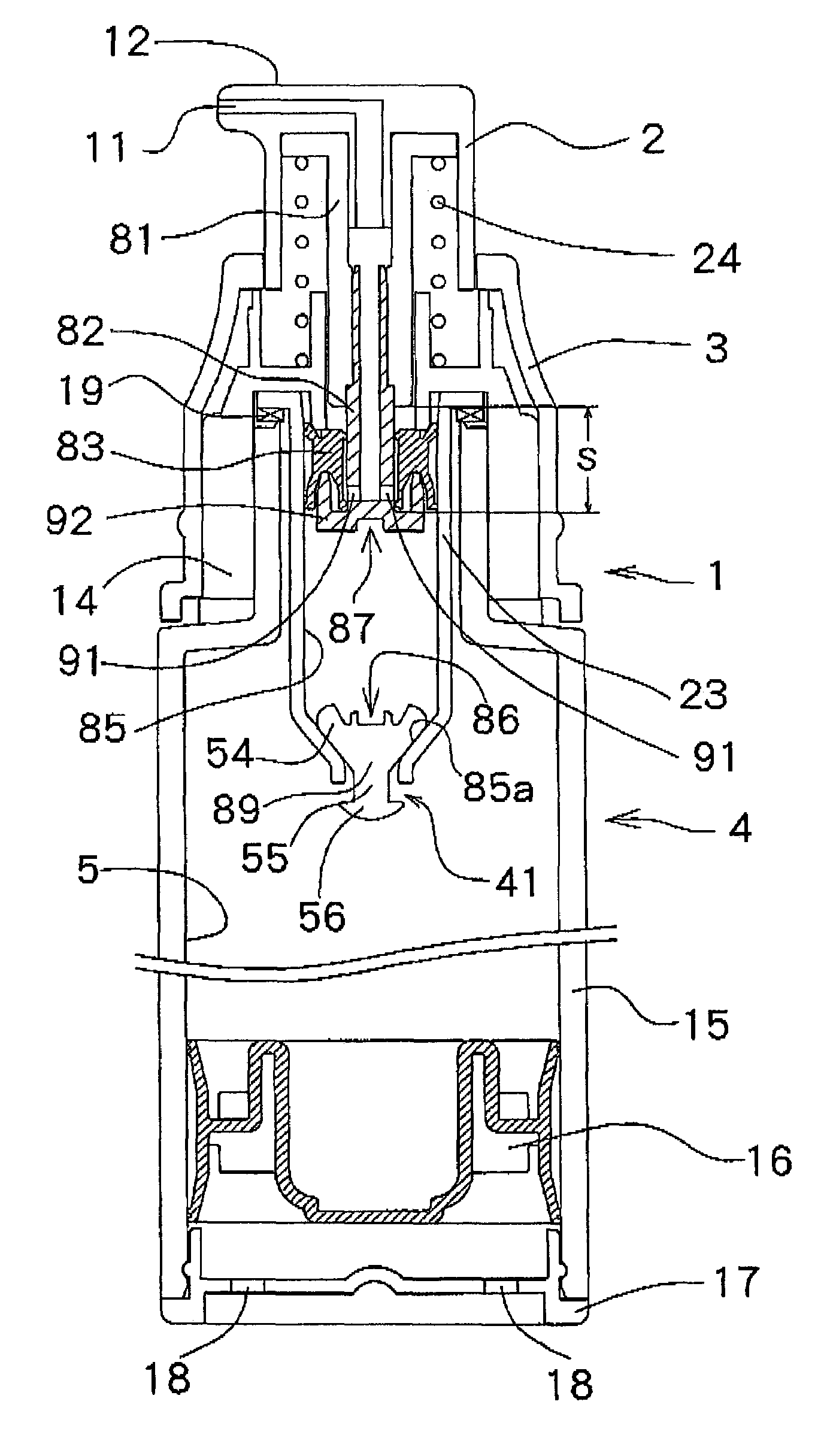
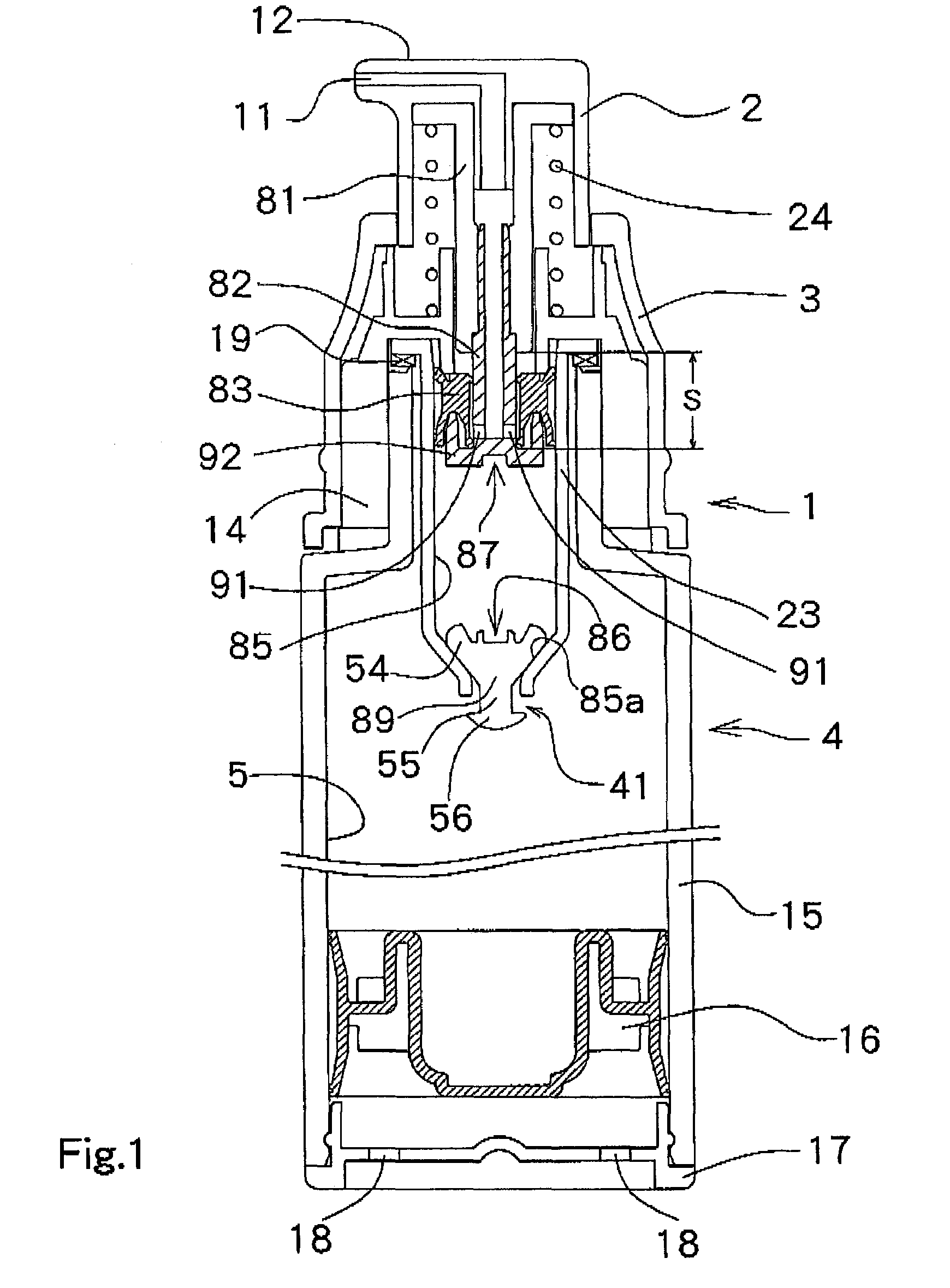
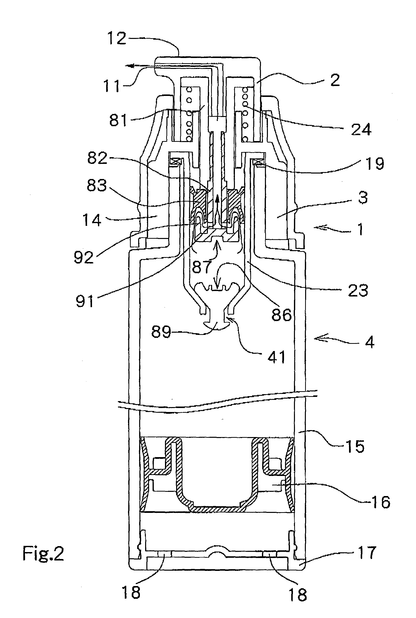
[0052]In the present invention, a cylinder mechanism of a comprises a cylinder filled with a fluid inside it and a piston reciprocating inside the cylinder, which is characterized in that, on an outer circumferential surface of the piston, a pair of liquidtight portions, each of which contacts an inner circumferential surface of the cylinder, are arranged in positions apart only by a certain distance and the contact portions in a pair of the liquidtight portions, which contact the inner circumferential surfaces of the cylinder, comprise a pair of convex portions arranged adjacently.

second embodiment

[0053]In a second embodiment, a cylinder mechanism of a fluid container comprises a cylinder filled with a fluid inside it and a piston reciprocating inside the cylinder, which is characterized in that, on an outer circumferential surface of the piston, a pair of liquidtight portions, each of which contacts an inner circumferential surface of the cylinder, are arranged in positions apart only by a certain distance and that, of a pair of the liquidtight portions, the contact portion of one liquidtight portion, which contacts the inner circumferential surface of the cylinder, comprises a pair of convex portions arranged adjacently, and the contact portion of the other liquidtight portion, which contacts the inner circumferential surface of the cylinder, comprises a single convex portion.

third embodiment

[0054]the present invention is characterized by comprising: A cylindrical main unit with a bottom, which has an opening portion at its bottom; a cylindrical portion having an external form smaller than the internal diameter of the opening portion at the main unit; a valve seat having a coupled portion, which couples the main unit and the cylindrical portion for fixing the cylindrical portion within the opening portion; a valve body having a valve portion which closes the opening portion by contacting the bottom of the main unit and opens the opening portion by separating from the bottom of the main unit, a guide portion having an external form smaller than the internal diameter of the cylindrical portion and a length longer than that of the cylindrical portion, which, by being inserted inside the cylindrical portion, guides a movement between a position at the valve portion which contacts the bottom of the main unit and a position which separates from the bottom, and a regulating po...


PUM


Abstract

A liquid-dispensing structure includes: an outer cylinder with a one-way valve at its lower end to allow a liquid to flow into the outer cylinder; a hollow piston being slidable inside the outer cylinder and having a pair of liquid-tight portions formed with circular convex portions around its outer circumferential surface in positions apart in an axial direction; and an inner cylinder for dispensing a liquid, which reciprocates inside the outer cylinder so that the piston moves in a piston-sliding area of the inner cylinder having an opening through which the liquid flows. The opening is closed when the piston is at a lower position and is opened when the piston is at an upper position.

Description

BACKGROUND OF THE INVENTION[0001]The present invention relates to a cylinder mechanism used for, for example, a fluid container such as a cosmetic container. Further, the present invention relates to a valve mechanism used for a container for a fluid or a liquid such as cosmetics.[0002]As such cylinder mechanisms, conventionally, a mechanism using a cylinder filled with a fluid therein and a piston sliding inside the cylinder is used.[0003]In the conventional cylinder mechanisms, it was difficult to reciprocate a piston smoothly while accomplishing sufficient liquidtightness. Additionally, to achieve a configuration in which a piston can be reciprocated smoothly while accomplishing liquidtightness, the piston needs to be manufactured with an extremely high degree of accuracy, which increases production costs.[0004]For this reason, the use of a configuration for moving a piston smoothly while accomplishing high liquidtightness by providing an O-ring contacting an inner circumferentia...

Claims


Application Information

Patent Timeline
IPC IPC(8): B05B11/00B65D83/76
CPCB05B11/0048B05B11/3023B05B11/3067B05B11/3074B05B11/028B05B11/1023B05B11/1067B05B11/1074B65D47/00
Inventor MASUDA, MASATOSHI
Owner MASUDA MASATOSHI
Why Eureka
Try Eureka