Cable safety system

a safety system and cable technology, applied in the field of high-speed barriers and safety systems, can solve the problems of increasing the risk of the vehicle running over the cable, being exposed to the hazards, and many cable safety systems, so as to reduce the risk of injury, and reduce the tension

Inactive Publication Date: 2005-11-08
TRINITY HIGHWAY PROD LLC
View PDF11 Cites 87 Cited by
  • Summary
  • Abstract
  • Description
  • Claims
  • Application Information

AI Technical Summary

Benefits of technology

[0010]Technical benefits of the present invention include providing a cable safety system that maintains engagement between posts and associated cables for a longer period of time as the posts are bent from their normal, generally vertical position during a vehicle impact. A cable safety system incorporating teachings of the present invention also minimizes the number of times an installer must to go to each post to position associated cables with desired vertical spacing relative to each other and an adjacent roadway. The present invention reduces both cost and time required to install a cable safety system. Cable safety system installers are exposed to reduced risk of injury by traffic because the present invention generally reduces the number of times installers must go to each support post.
[0011]For some applications, a cable safety system formed in accordance with teachings of the present invention may require twenty percent (20%) fewer support posts and/or require placing less tension on associated cables as compared with prior cable safety systems. Support posts formed in accordance with teachings of the present invention preferably have generally symmetrical cross sections which are often more suitable for use as a single barrier along the edge of a roadway or for use as a median barrier. Such support posts often provide increased safety for all types of vehicles by optimizing the shape of each support post (“softer” support posts) to minimize vehicle damage and providing increased vertical spread between associated cables.
[0012]Additional technical benefits of the present invention include optimizing design of a cable safety system to provide satisfactory deflection characteristics with less tension required in the cables and greater spacing between support posts. Repairs may more easily be made to the cable safety system after a vehicle impact. The need for periodic re-tensioning of cables may be reduced or eliminated by the present invention.
[0013

Problems solved by technology

One recognized limitation of many cable safety systems is excessive deflection of associated cables during a vehicle impact.
Large deflection during a vehicle impact also increases the risk of the vehicle running over the cables and being exposed to the hazard which required installation of the cable safety system.
Calculating performance of many cable s

Method used


Image

  • Cable safety system
  • Cable safety system
  • Cable safety system

Examples


Embodiment Construction

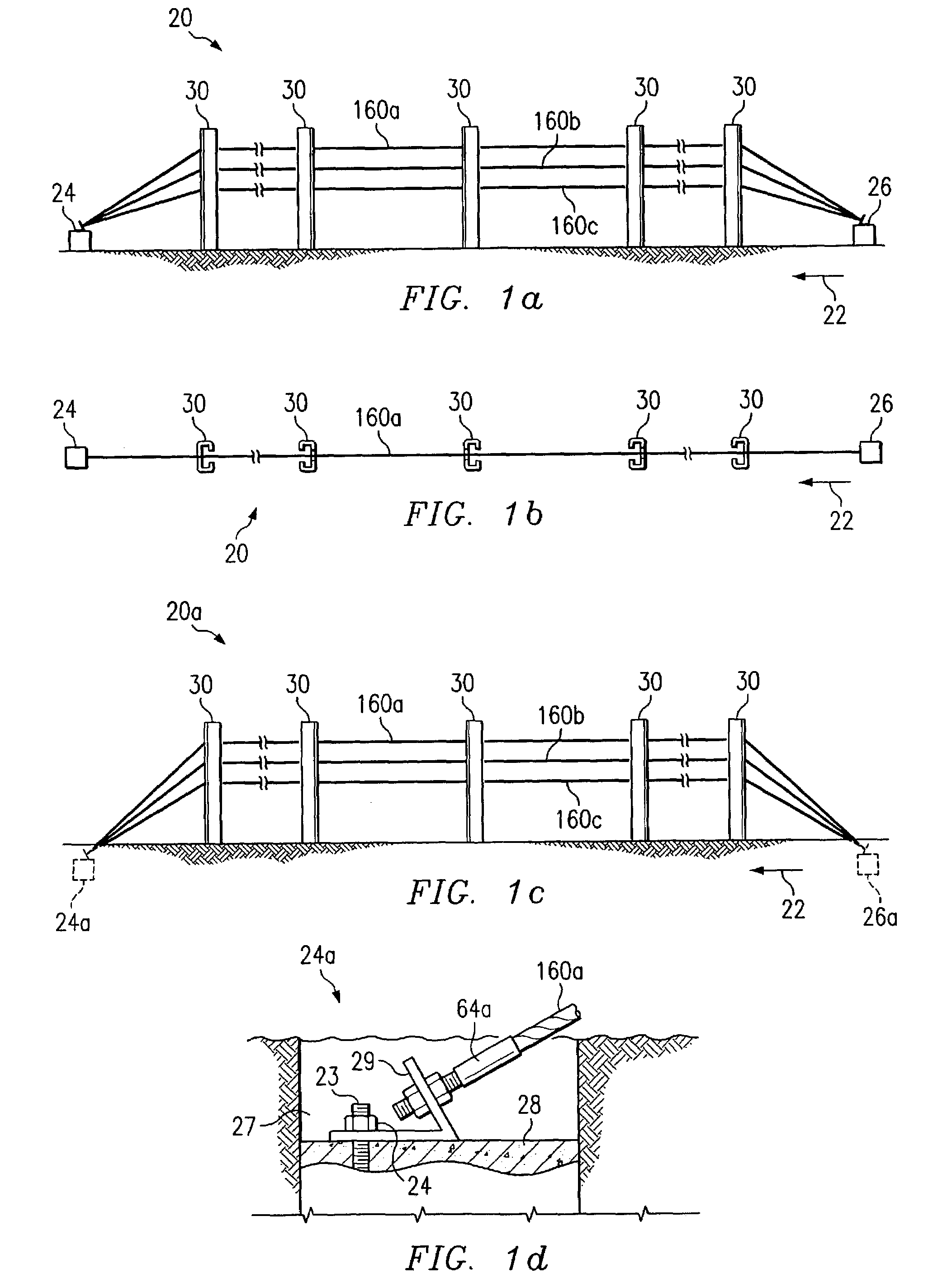
[0032]Preferred embodiments of the invention and its advantages are best understood by reference to FIGS. 1a–11 wherein like reference numbers indicate like features.

[0033]The terms “safety system” or “safety systems” and “barrier” or “barriers” may be used throughout this application to include any type of safety system and / or barrier which may be formed at least in part using cables and support posts incorporating teachings of the present invention. The term “roadway” may be used throughout this application to include any highway, roadway or path satisfactory for vehicle traffic. Safety systems and barriers incorporating teachings of the present invention may be installed in median strips or along shoulders of highways, roadways or any other path which is likely to encounter vehicular traffic.

[0034]Various aspects of the present invention will be described with respect to cable safety systems 20 and 20a. However, teachings of the present invention may be used to form a wide variet...


PUM


Abstract

A safety system including cables and support posts is provided. The safety system may be used to prevent vehicles from impacting with an associated roadside hazard. The safety system will typically maintain engagement between associated cables and support posts for a longer period of time as the posts are bent during a vehicle impact.

Description

RELATED APPLICATION[0001]This application claims the benefit of previously filed provisional application entitled “Cable Safety System,” Ser. No. 60 / 383,653, filing date May 28, 2002.TECHNICAL FIELD[0002]The present invention is related to highway barriers and safety systems and more particularly to cable safety systems and associated posts.BACKGROUND OF THE INVENTION[0003]Cable safety systems and cable barriers have been installed along edges of roadways and highways for many years. Cable safety systems and cable barriers have also been installed along medians between roadways and / or highways. Cable safety systems generally include one or more horizontal cables attached to support posts. For some applications cable safety systems and cable barriers may reduce damage to an impacting vehicle and / or injury to occupants of the impacting vehicle as compared with other types of highway safety systems and highway barriers.[0004]Cable safety systems are often designed and installed with at...

Claims


Application Information

Patent Timeline
IPC IPC(8): E01F15/02E01F15/06
CPCE01F15/06
Inventor BERGENDAHL, PETER
Owner TRINITY HIGHWAY PROD LLC
Why Eureka
Try Eureka