Panel light source device and display device

a technology of light source device and display device, which is applied in the direction of lighting and heating apparatus, instruments, mechanical equipment, etc., can solve the problems of display irregularity, light source device with such a problem cannot be used as a panel light source, and achieve the effect of low cos

Inactive Publication Date: 2005-11-08
MITSUBISHI ELECTRIC CORP
View PDF12 Cites 25 Cited by
  • Summary
  • Abstract
  • Description
  • Claims
  • Application Information

AI Technical Summary

Benefits of technology

[0016]It is an object of the present invention to provide a panel light source device having a construction preventing or suppressing a clearance between a reflecting sheet and a light guide plate from occurring. It is another object of the present invention to provide a panel light source device having a construction preventing or suppressing a misregistration between a reflecting sheet and a light guide plate from occurring. It is still another object of the present invention to provide a panel light source device having a construction in which an external force is hard to be transmitted to an optical sheet. It is yet another object of the present invention to provide the panel light source devices at a low cost. It is yet another object of the present invention to provide a display equipped with any of the panel light source devices.

Problems solved by technology

Furthermore, light evaded from the clearance becomes stray light and the stray light appearing on the light emitting surface causes luminance irregularity of the light source device, having led, in turn, to a problem of display irregularity when such a light source device is adopted in a liquid crystal display device.
Since this kind of display irregularity is extremely severe, a light source device with such a problem could not be used as a panel light source without an improvement thereon.
Moreover, when an external force is imposed on the front face of the front face case 6, the front face case 6 is deformed to press the optical sheet 2 toward the light guide plate 1 side, so that a problem has arisen that a display quality is greatly degraded.
If a material strong in restoring force against bending is used as that of the reflecting sheet 5, it is not easy to suppressing occurrence of a clearance with the double-sided tape 8.
In addition, the double-sided tape 8 adhered to the light guide plate 1 causes unexpected reflection in the light guide plate 1 to disable uniform luminance on the light emitting surface, having again resulted in a problem of reduction in luminance.
For this reason, a problem has arisen that a clearance is easy to occur between the reflecting sheet 5 and the light guiding plate 1.
In addition, when a force was imposed on a case, the case in turn pressed the optical sheet 2 to thereby, greatly degrade a display quality.

Method used


Image

  • Panel light source device and display device
  • Panel light source device and display device
  • Panel light source device and display device

Examples


first embodiment

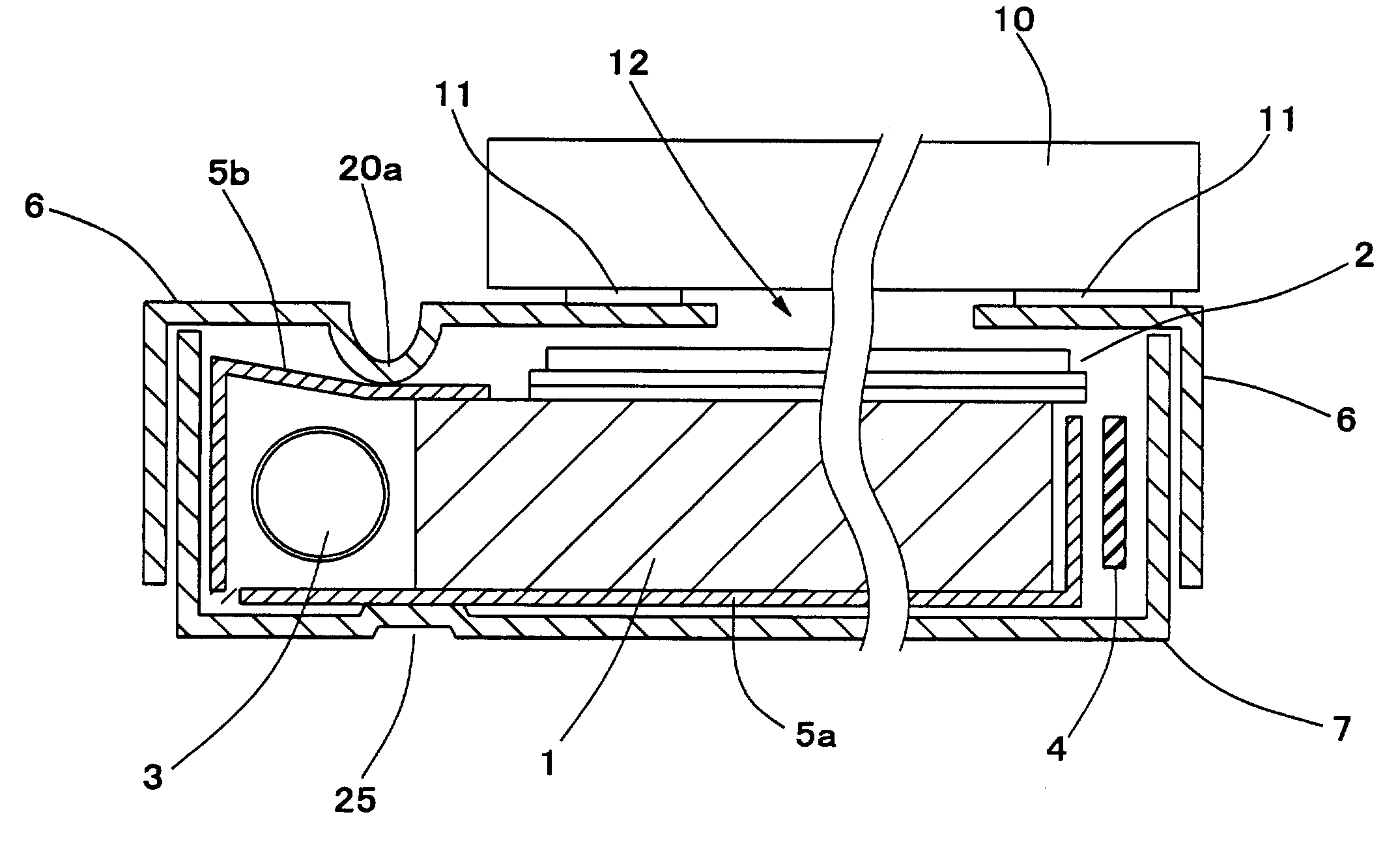
[0054]FIG. 4 is a sectional view showing an example construction of a display device according to a first embodiment of the present invention. In the figure, a numerical reference 1 indicate a light guide plate, 2 an optical sheet, 3 an light emitter, 4 a wire, 5 a reflecting sheet, 6 a front face case, 7 a rear face case, 10 a liquid crystal panel, 11 a double-sided tape, 12 an opening section and 20 a reflecting sheet contact section. The light guide plate 1, the optical sheet 2, the light emitter 3, the wire 4 and the reflecting sheet 5 are housed in a composite case obtained by engaging the front face case 6 and the rear face case 7 with each other to construct a panel light source device, and the panel light source device is mounted to the liquid crystal panel 10 with the double-sided tape 11 to construct a liquid crystal display device.

[0055]The light guide plate 1 is a transparent light guide made of an acrylic resin or the like having a prescribed refractive index and formed...

second embodiment

[0073]While in the first embodiment, description is given of the case where deep drawing is applied to the front face case 6 to form the reflecting sheet contact sections 20, description in this embodiment will be given of a case where bending is applied to form a reflecting sheet contact section.

[0074]FIG. 9 is a sectional view showing an example construction of a panel light source device according to a second embodiment of the present invention. In the figure, a numerical reference 1 indicates a light guide plate, 2 an optical sheet, 3 a light emitter, 4 a wire, 5 a reflecting sheet, 6 a front face case, 7 a rear face case and 21 a reflecting sheet contact section. The reflecting sheet contact section 21, similar to the reflecting sheet contact section 20 of FIG. 4, is a contact section formed on the front face of the front face case 6 so that the front face of the front face case is brought into contact with the reflecting sheet 5 housed in a composite case. The reflecting sheet...

third embodiment

[0076]While in the first and second embodiments, descriptions are given of the example cases where the reflecting sheet contact sections 20 and 21 are brought into contact with the reflecting sheet 5 in the light emitter 3 side thereof, spaced apart from the light guide plate 1, description in this embodiment will be given of a case where a reflecting sheet contact section is brought into contact with the reflecting sheet 5 on the light guide plate 1.

[0077]FIG. 10 is a sectional view showing an example construction of a panel light source device according to a third embodiment of the present invention. In the figure, a numerical reference 1 indicates a light guide plate, 2 an optical sheet, 3 a light emitter, 4 a wire, 5 a reflecting sheet, 6 a front face case, 7 a rear face case and 22 a reflecting sheet contact section. The reflecting sheet contact section 22, similar to the case of the first embodiment (FIG. 4), is a contact section formed on the front face of the front face case...


PUM

PropertyMeasurementUnit
power consumptionaaaaaaaaaa
weightaaaaaaaaaa
luminanceaaaaaaaaaa

Abstract

A panel light source device has a construction which not only prevents a gap or clearance between a reflecting sheet 5 and a light guide plate 1 from occurring, but also improves the luminance and uniformity of a light emitting surface, at a low cost. A panel light source device includes a light guide plate 1 on a front face of which an optical sheet 2 is provided, a light emitter 3 to cause light to enter a side face of the light guide plate 1, a reflecting sheet 5, provided facing a rear face of the light guide plate 1, and an end of which extends around the light emitter 3 to reach the front face of the light guide plate, and a case 6, not only housing the light guide plate 1, the light emitter 3 and the reflecting sheet 5, but also equipped with a reflecting sheet contact section 20, causing part of a front face thereof to recede toward a rear face side thereof, to bring the part of a front face thereof into contact with the reflecting sheet 5.

Description

BACKGROUND OF THE INVENTION[0001]1. Field of the Invention[0002]The present invention relates to a panel light source device and a display device, and more particularly to improvement on a panel light source device, which are used in a display device for presenting letters, an image and others thereon, for example, a liquid crystal display device, and on a display device including this panel light source device.[0003]2. Description of the Related Art[0004]A liquid crystal display device has features such as being slim, light, low in power consumption and others in comparison with other kinds of displays, and has been widely used as displays for use in various applications such as those starting with a computer, followed by portable terminals including a portable telephone, a car navigation terminal and others. In a case of a liquid crystal display device, since a liquid crystal panel on which image information on each pixel is reproduced does not emit light by itself, a light source...

Claims


Application Information

Patent Timeline
Patent Type & Authority Patents(United States)
IPC IPC(8): F21V8/00F21Y103/00G02F1/13357
CPCG02B6/0055G02B6/0088G02B6/009G02B6/0083G02F1/133615G02F2001/133317G02F1/133317G02F1/1335
Inventor ITO, ATSUSHIKAWANO, MASAYUKI
Owner MITSUBISHI ELECTRIC CORP
Why Eureka
Try Eureka