Illuminated touch switch

a technology of illuminated switch and touch, which is applied in the direction of electric switches, electric switches, electric apparatus, etc., can solve the problems of -luminescent planar lamps, the requirement for an external cover, and the inability of electric-luminescent planar lamps to produce only one color

Active Publication Date: 2005-11-08
WESTINGHOUSE AIR BRAKE TECH CORP
View PDF11 Cites 53 Cited by
  • Summary
  • Abstract
  • Description
  • Claims
  • Application Information

AI Technical Summary

Benefits of technology

[0016]It is additional object of the present invention to provide an illuminated touch switch device which incorporates protection from external environmental factors.

Problems solved by technology

One disadvantage of the switch taught by U.S. Pat. No. 5,118,910 is that, as is well known, electro-luminescent planar lamps are capable of producing only one color.
The second disadvantage is that an electro-luminescent planar lamp requires an inverter to convert the input electricity to the required AC electricity of the necessary frequency and voltage to operate the lamp.
The third disadvantage is associated with the requirement for an external cover, particularly when subjected to the environmental elements such as moisture and dirt.

Method used


Image

  • Illuminated touch switch
  • Illuminated touch switch
  • Illuminated touch switch

Examples


first embodiment

[0022]FIG. 5 is a schematic diagram particluraly showing the control circuit of the present invention;

second embodiment

[0023]FIG. 6 is a schematic diagram particluraly showing the control circuit of the present invention;

third embodiment

[0024]FIG. 7 is a schematic diagram particluraly showing the control circuit of the present invention;

[0025]FIG. 8 is a schematic diagram particluraly showing the prefered embodiment of the control circuit of of the instant invention;

[0026]FIG. 9 is a schematic diagram of the control circuit particularly showing application of bi-color light emiting diodes of the alternative embodiment;

[0027]FIG. 10 is partial perspective view of the touch switch of the present invention particularly showing an electrical connection means of the alternative embodiment; and

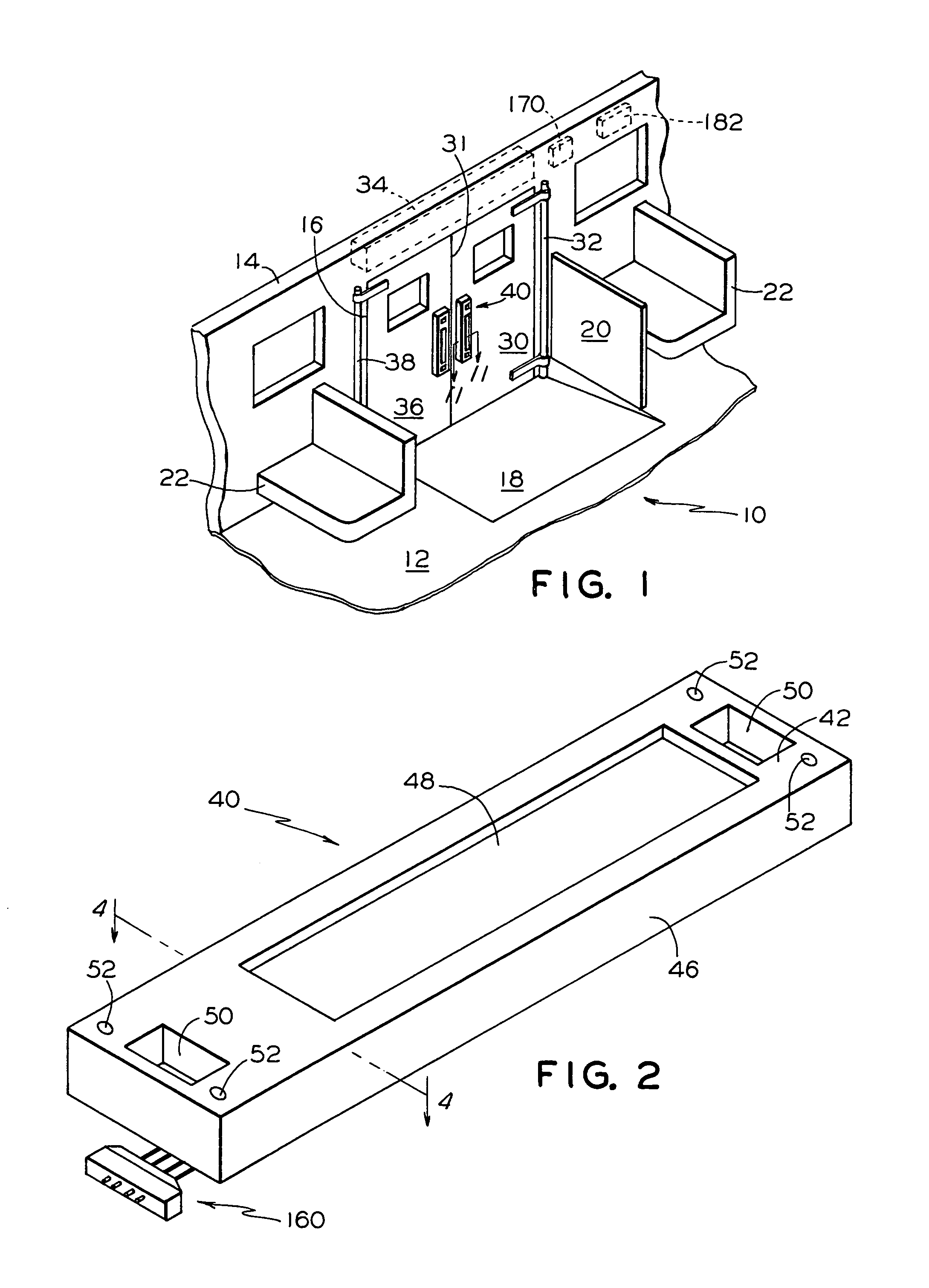
[0028]FIG. 11 is a partial cross-sectional view of the touch switch of the present invention along lines 11—11 in FIG. 1, particularly showing touch switch mounting of the alternative embodiment.


PUM


Abstract

An illuminated touch switch has a touch sensitive area and a plurality of light emitting diodes arranged in a predetermined pattern. The touch switch includes a first rigid circuit board with a first electrical conductor and a second flexible circuit board with a second electrical conductor separated by a spacer of a predetermined thickness. Both conductors are aligned with the touch sensitive area and are coupled from the applied pressure providing an output signal. Light emitting diodes illuminate a single color light to indicate an enabled condition of the touch sensitive area.

Description

FIELD OF THE INVENTION[0001]The present invention relates, in general, to an illuminated touch activated switch device and, more particularly, the instant invention relates to an illuminated touch activated switch device of a membrane type construction and, still more particularly, the instant invention relates to an illuminated touch activated switch device for use in a transit vehicle.BACKGROUND OF THE INVENTION[0002]The following background information is provided to assist the reader to understand the environment in which the invention will typically be used. The terms used herein are not intended to be limited to any particular narrow interpretation unless specifically stated otherwise in this document.[0003]It is well known that pressure activated switches have been used in a variety of safety and equipment control applications. For example, U.S. Pat. No. 4,088,856 entitled “Perimeter Safety Switch Mounted To Support Disposed Remote From The Machine Body” teaches a perimeter s...

Claims


Application Information

Patent Timeline
Patent Type & Authority Patents(United States)
IPC IPC(8): H01H9/00H01H9/02H01H13/02
CPCH01H13/023H01H9/0271H01H2219/014
Inventor URMAN, ROBERT
Owner WESTINGHOUSE AIR BRAKE TECH CORP
Why Eureka
Try Eureka