Method and system for calibrating a look-down linear array scanner utilizing a folded optical path

a linear array and scanning scanner technology, applied in the field of system and method for calibrating a digital imaging device, can solve the problems of difficult to perform further image processing, recognition (ocr) operations, and prior art look-down digital imaging devices generally do not include a mechanism for calibrating such devices, and achieve the effect of accurate calibration

Inactive Publication Date: 2005-11-08
HEWLETT PACKARD DEV CO LP
View PDF15 Cites 19 Cited by
  • Summary
  • Abstract
  • Description
  • Claims
  • Application Information

AI Technical Summary

Benefits of technology

[0008]These and other objects, features and technical advantages are achieved by a system and method which provide a look-down digital imaging device capable of scanning a calibration area included within such look-down digital imaging device to capture image data for the calibration area and calibrate itself based on analysis of such captured image data. More specifically, a preferred embodiment includes a calibration area that is integrated internally within the look-down digital imaging device. When performing calibration in such a preferred embodiment, the scan head of the look-down digital imaging device is operable to align itself with the calibration area to allow for a scan of the calibration area (i.e., the capture of digital image data of the calibration area). In one embodiment, a look-down digital imaging device does not achieve a focused scan of the calibration area, but is capable of utilizing captured unfocused digital imaging data for calibration. In a preferred embodiment, a look-down digital imaging device achieves a focused scan of the calibration area, thereby enabling a further accurate calibration. More specifically, a preferred embodiment folds the optical path of the reflected light from the calibration area in order to have the optical path of such calibration area accurately mimic the optical path of an original to be scanned, thereby allowing for focused calibration to be achieved.

Problems solved by technology

As a result, it may be difficult to perform further image processing, such as optical character recognition (OCR) operations, of such an inaccurate digital image.
However, look-down digital imaging devices of the prior art generally do not include a mechanism for calibrating such devices.
However, such a calibration path is generally not available in look-down digital imaging devices.
However, this technique requires action by the user to perform calibration of the look-down digital imaging device.
Accordingly, such a calibration technique would be inefficient, inconvenient and undesirable to a user, especially if calibration of the look-down digital imaging device is desired before every scan of an original.
Furthermore, because such calibration technique relies on a scan of an image external to the look-down digital imaging device, such calibration technique is likely not as reliably accurate as is desired.
That is, this calibration technique is not performed within such a controlled environment as is available within the digital imaging device itself.
Thus, external factors such as the calibration image being improperly positioned on the target area or the calibration image being dirty or otherwise damaged, as examples, may prevent the look-down digital imaging device from being properly calibrated.

Method used


Image

  • Method and system for calibrating a look-down linear array scanner utilizing a folded optical path
  • Method and system for calibrating a look-down linear array scanner utilizing a folded optical path
  • Method and system for calibrating a look-down linear array scanner utilizing a folded optical path

Examples


Embodiment Construction

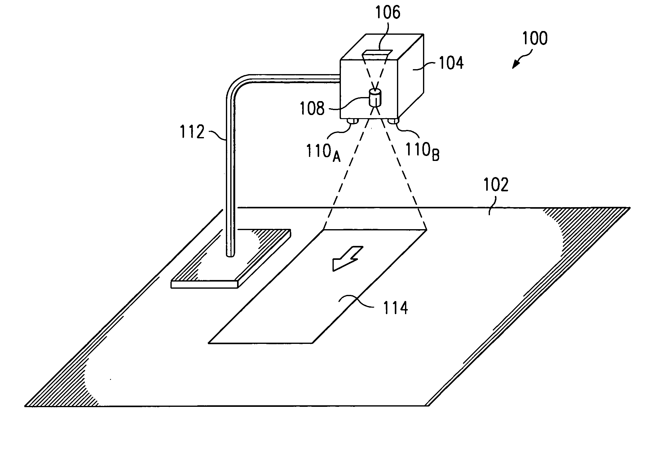
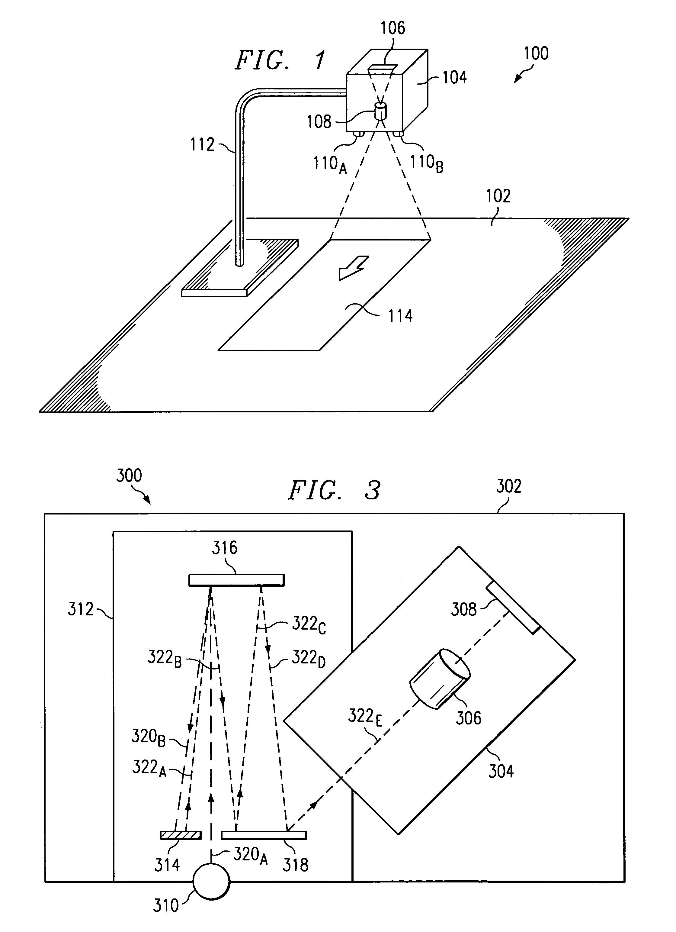
[0017]Turning to FIG. 1, an exemplary look-down digital imaging device 100 is shown. Look-down digital imaging device 100 is suspended over a desktop (or other surface) 102 by, for example, frame 112. An original (e.g., a document page) 114 is positioned face up on desktop 102 below look-down digital imaging device 100. In the exemplary implementation of FIG. 1, look-down digital imaging device 100 includes light sources 110A and 110B for illuminating original 114. Look-down digital imaging device 100 further comprises housing 104 that includes a lens 108 for focusing reflected light from original 114 onto sensor 106. Preferably, sensor 106 is a linear sensor (or “linear array”) for receiving light reflected from original 114 and converting the light to electrical signals based on the intensity of such reflected light. Most preferably, sensor 106 utilizes a tri-liner color coupled-charge device (CCD) array (or similar imaging technology) to provide a high resolution scan of an area ...


PUM


Abstract

A system and method are disclosed which provide a look-down digital imaging device capable of scanning a calibration area included within such look-down digital imaging device to capture image data for the calibration area and calibrate itself based on analysis of such captured image data. More specifically, a preferred embodiment includes a calibration area that is integrated internally within the look-down digital imaging device. When performing calibration in such a preferred embodiment, the scan head of the look-down digital imaging device is operable to align itself with the calibration area to allow for a scan of the calibration area (i.e., the capture of digital image data of the calibration area). In one embodiment, a look-down digital imaging device does not achieve a focused scan of the calibration area, but is capable of utilizing captured unfocused digital imaging data for calibration. In a preferred embodiment, a look-down digital imaging device achieves a focused scan of the calibration area, thereby enabling a further accurate calibration. More specifically, a preferred embodiment folds the optical path of the reflected light from the calibration area in order to have the optical path of such calibration area accurately mimic the optical path of an original to be scanned, thereby allowing for focused calibration to be achieved.

Description

TECHNICAL FIELD[0001]The present invention relates in general to a system and method for calibrating a digital imaging device, and in specific to a method and system for calibrating a look-down digital imaging device.BACKGROUND[0002]Various types of digital image capture (or image reading) devices are available in the prior art. More particularly, various types of image capture devices are available in the prior art for obtaining a digital image of an original image. For example, image capture devices such as scanners (both handheld and flatbed) for personal computers, digital cameras, facsimile machines, and digital copying machines are available in the prior art. Some of these traditional digital imaging devices perform calibration before each capture of a digital image, upon power up, periodically, or according to some other appropriate regime to ensure that the digital imaging devices are properly calibrated, thereby enabling the digital imaging devices to capture high quality d...

Claims


Application Information

Patent Timeline
Patent Type & Authority Patents(United States)
IPC IPC(8): H04N1/03H04N1/19G06T1/00H04N1/04
CPCH04N1/03H04N1/0303H04N1/0305H04N1/19H04N2201/02497H04N2201/0436H04N2201/044
Inventor GANN, ROBERT G
Owner HEWLETT PACKARD DEV CO LP
Why Eureka
Try Eureka