Compact imaging head and high speed multi-head laser imaging assembly and method

a multi-head laser and compact technology, applied in the field of compact imaging heads and high-speed multi-head laser imaging assemblies, can solve the problems of power limitations of conventional external drums employing spatial modulators, limited power of conventional internal drum systems, and limited spot production, so as to reduce the width of the head

Inactive Publication Date: 2005-11-08
KODAK POLYCHROME GRAPHICS
View PDF16 Cites 2 Cited by
  • Summary
  • Abstract
  • Description
  • Claims
  • Application Information

AI Technical Summary

Benefits of technology

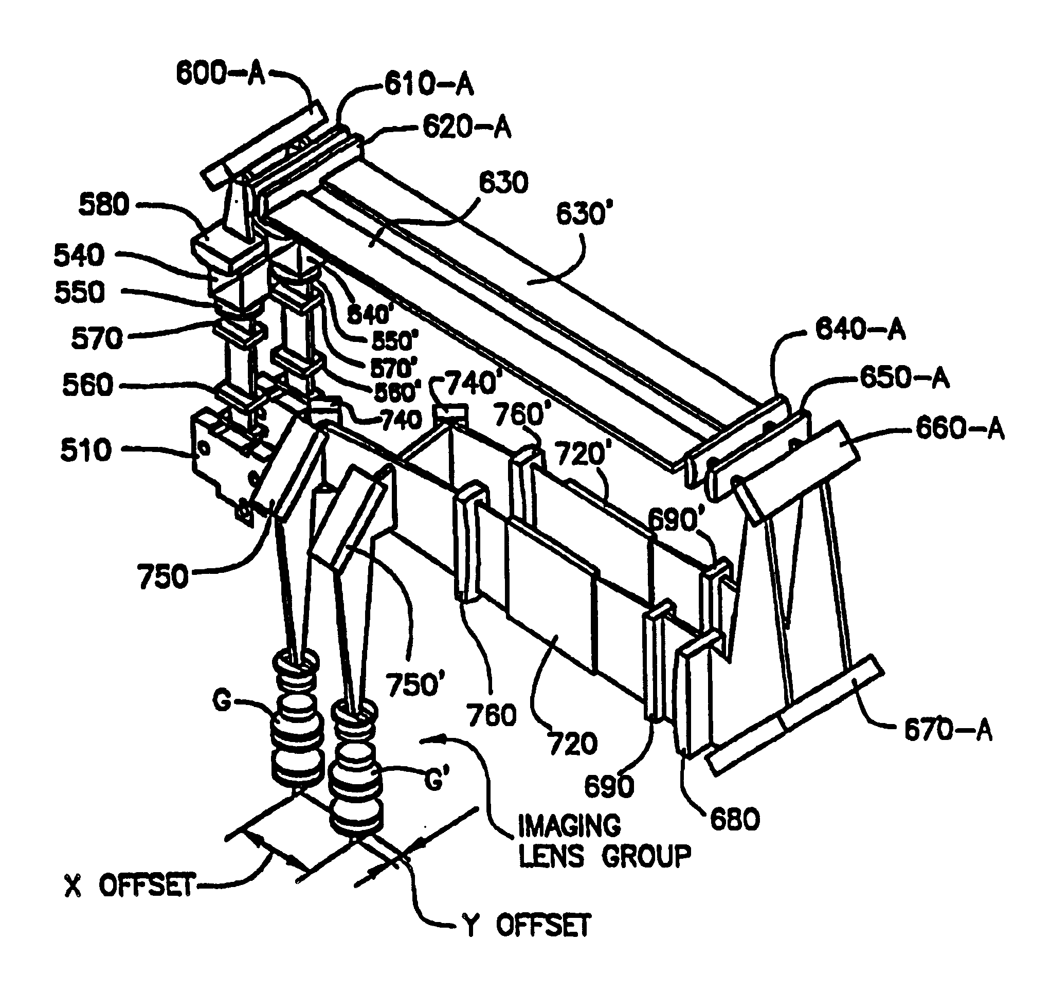
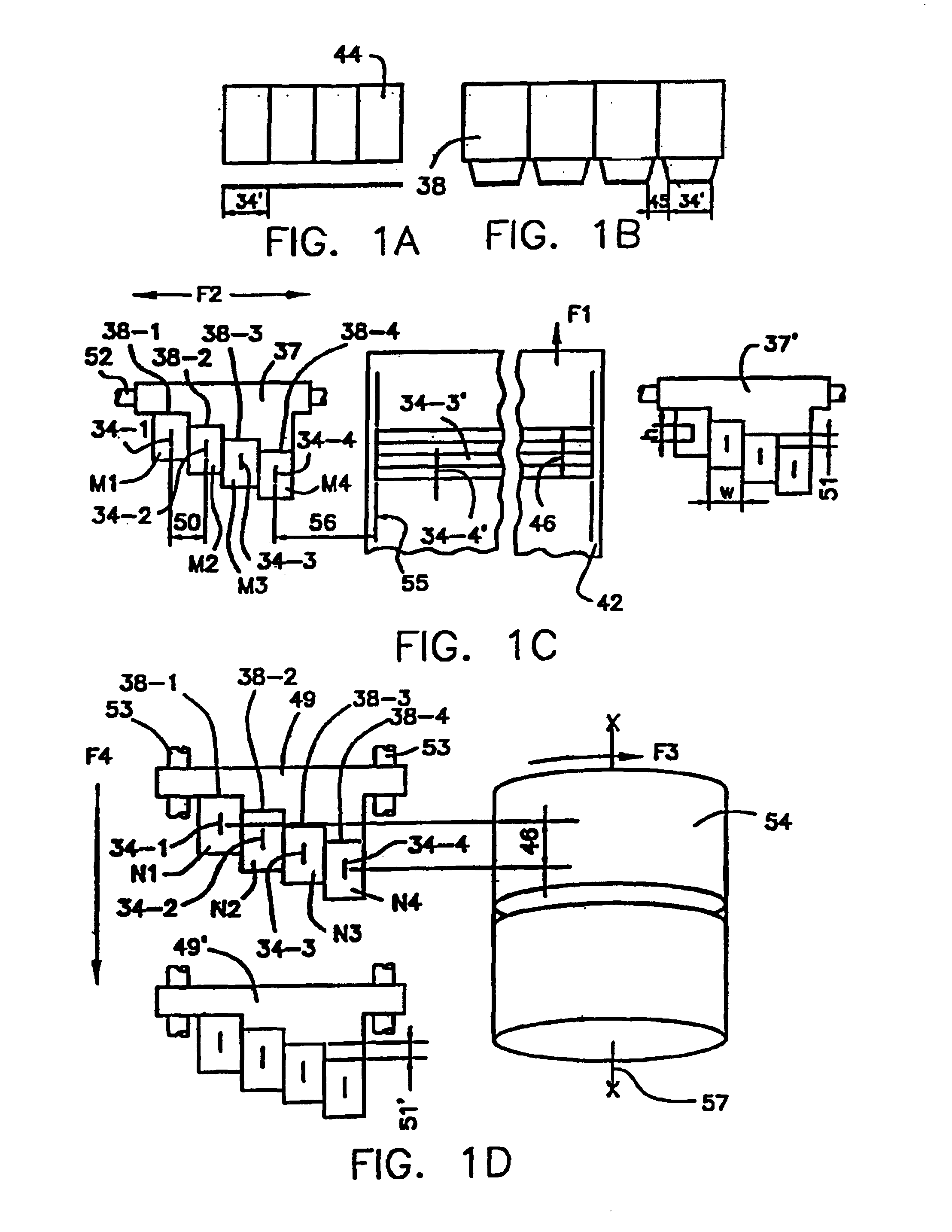
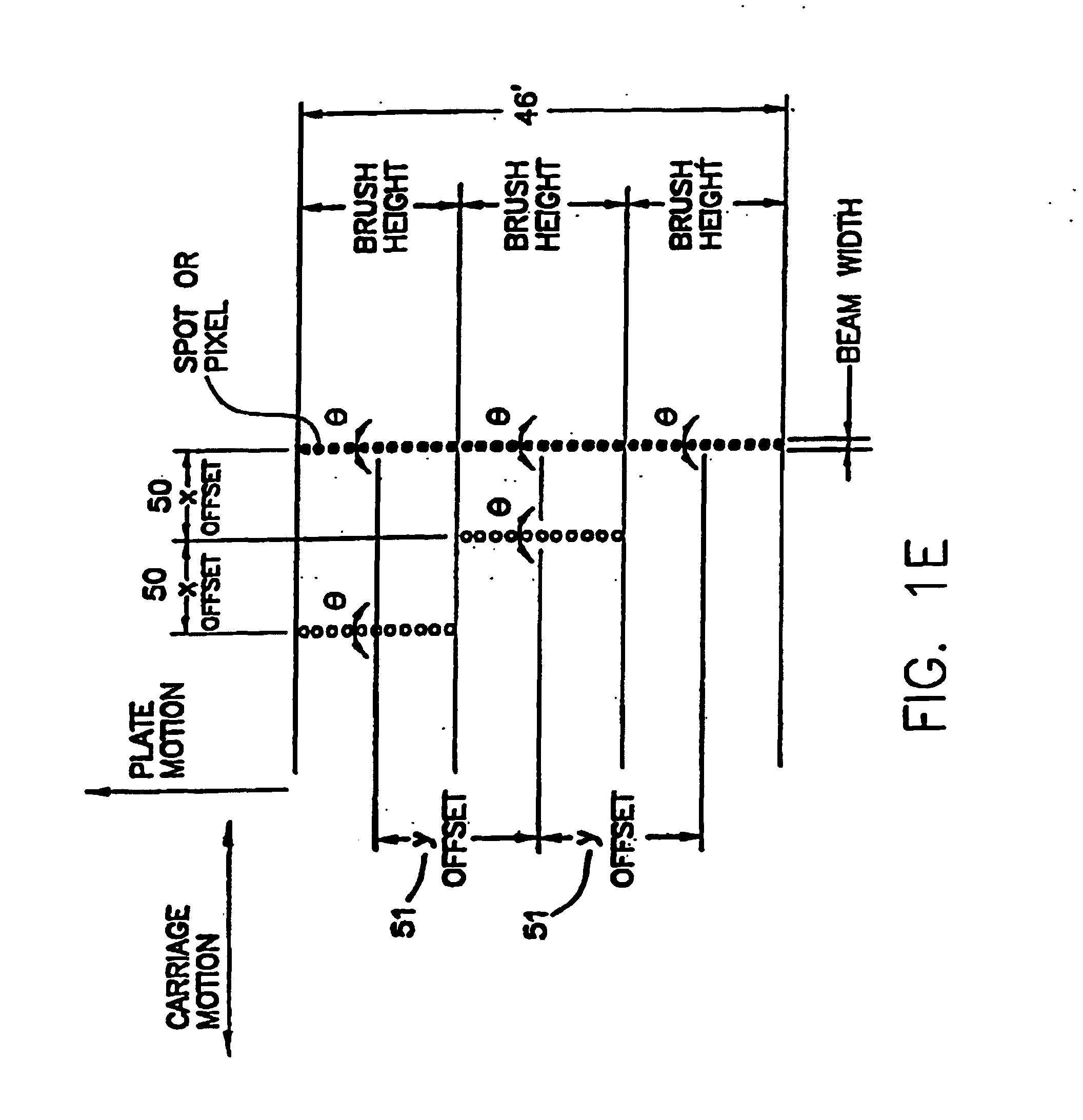
The patent describes a device that uses multiple optical heads to scan a printing plate and create an image. Each head has a laser source, modulator, and projection optics to project the image onto the plate. The heads are mounted on a carriage that moves back and forth, creating a brush-like effect as it moves. Each head can be adjusted for height, position, and intensity, and the carriages work together to create a wider swath of pixels. The device also generates pulses to indicate its position relative to the plate edges. The movements between the carriage and the plate are controlled by electronic means. The technical effect of this device is to allow for precise and efficient printing of images onto photosensitive plates.

Problems solved by technology

The technical problem addressed in this patent is the limitations of conventional thermal offset printing plate systems, particularly in terms of their productivity and the number of spots generated using a laser beam. The patent proposes a system and method that can overcome these limitations by increasing the power and sensitivity of the laser source, and by employing multiple imaging heads to produce a continuous scan line and avoid gaps in the overall scan line.

Method used


Image

  • Compact imaging head and high speed multi-head laser imaging assembly and method
  • Compact imaging head and high speed multi-head laser imaging assembly and method
  • Compact imaging head and high speed multi-head laser imaging assembly and method

Examples


Embodiment Construction

[0031]This invention and its various embodiments will become apparent from the following detailed description and specific references to the accompanying figures.

Compact Imaging Modules

[0032]FIGS. 2A and 2B show enlarged side views of an exemplary compact imaging module or head 36 which may be used in the assembly and method of the present invention. FIGS. 3A-3C show exploded elevation views of different sections of the module 36 illustrated in FIGS. 2A and 213, located on different respective planes. This module 36 has a laser source 10 (typically a laser bar or laser diode array comprising a plurality of emitters) emitting a bundle of rays 5 (see FIG. 2A), and arranged thereon which is attached to a support arrangement (not shown in FIGS. 2A and 2B). The laser source 10 described herein is cooled by a liquid flowing through micro channels. Such as laser source may be obtained from Jenoptik Laserdiode, GmbH, as type JOLD-32-CAFC-1L, having a power of 32 watts. This particular laser...


PUM


Abstract

An optical head having a laser source of beams at an input end and image forming beams at an output end and a plurality of optical components arranged along the beams between the input and output ends to obtain an image on a photosensitive printing plate from the beams. The optical components include reflecting surfaces adapted to fold the beams several times between the input and output ends times in such a way as to reduce the width and height of the optical head. The folded beams are located in a plurality of parallel surfaces perpendicular to the image formed on the photosensitive printing plate. The optical head further includes optical components adapted to adjust the width, location, orientation and intensity of the image from the beams.

Description


Claims


Application Information

Patent Timeline
Owner KODAK POLYCHROME GRAPHICS
Why Eureka
Try Eureka