Method and apparatus for synchronizing a vehicle lift

a technology for vehicle lifts and synchronization, applied in the direction of elevators, servomotors, instruments, etc., can solve the problems of significant problems such as differences in the vertical positions of independent superstructures

Inactive Publication Date: 2005-11-15
ROTARY ELEVATOR
View PDF35 Cites 32 Cited by
  • Summary
  • Abstract
  • Description
  • Claims
  • Application Information

AI Technical Summary

Problems solved by technology

Differences in the respective vertical positions of the independently superstructures can pose significant problems.

Method used


Image

  • Method and apparatus for synchronizing a vehicle lift
  • Method and apparatus for synchronizing a vehicle lift
  • Method and apparatus for synchronizing a vehicle lift

Examples


Embodiment Construction

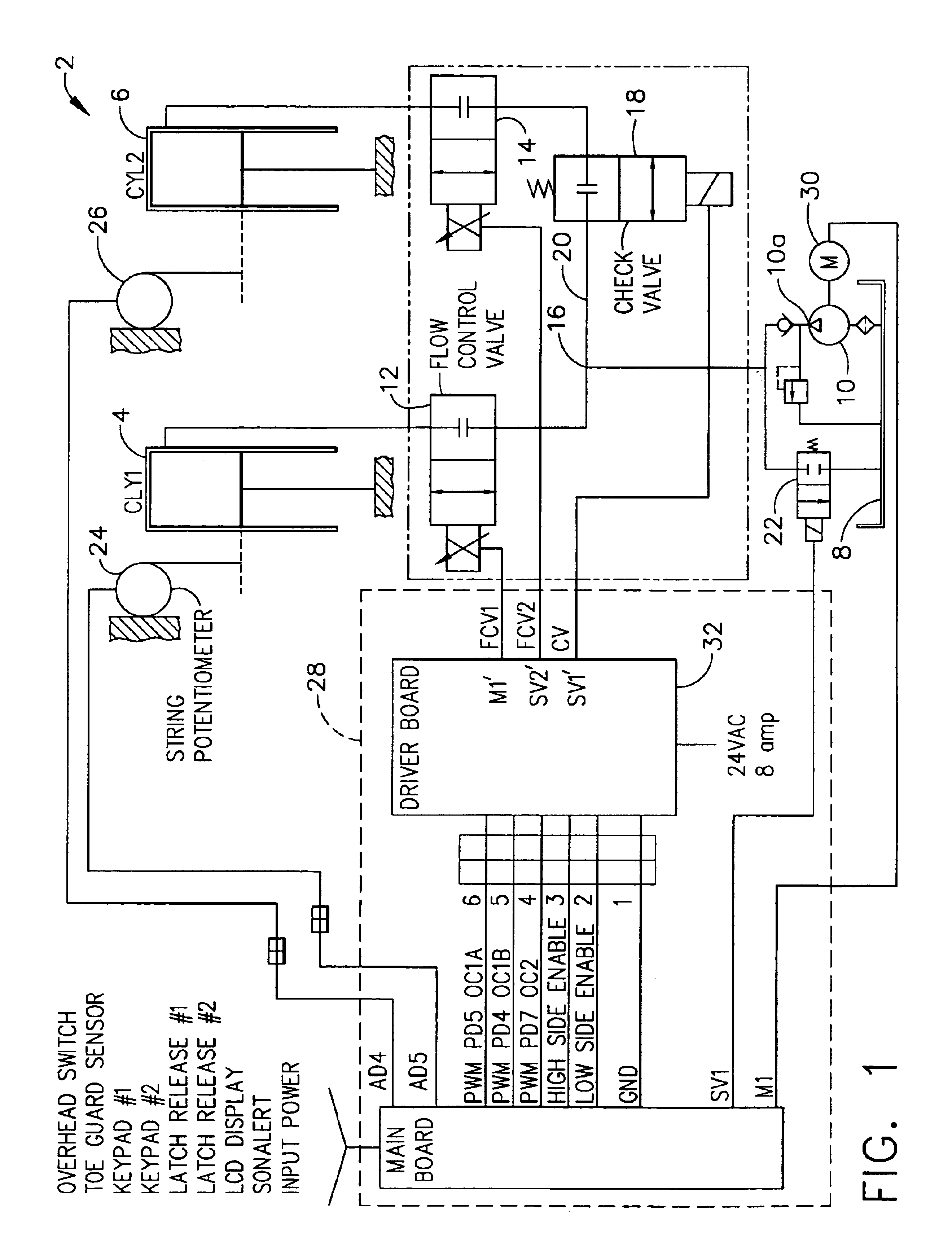
[0016]Referring now to the drawings in detail, wherein like numerals indicate the same elements throughout the views, FIG. 1 illustrates a vehicle lift, generally indicated at 2. Lift 2 is illustrated as a two post lift, including a pair of independently moveable actuators 4 and 6 which cause the respective superstructures (not shown) to move. In the depicted embodiment, first and second actuators 4 and 6 are illustrated as respective hydraulic cylinders, although they may be any actuator suitable for the control system. First and second actuators 4 and 6 are in fluid communication with a source of hydraulic fluid 8. Pressurized hydraulic fluid is provided by pump 10 at discharge 10a. Each actuator 4 and 6 has a respective proportional flow control valve 12 and 14 interposed between its actuator and source of hydraulic fluid 8.

[0017]The hydraulic fluid flow is divided at 16, with a portion of the flow going to (from, when lowered) each respective actuator 4 and 6 as controlled by fi...


PUM


Abstract

A vehicle lift control maintains multiple points of a lift system within the same horizontal plane during vertical movement of the lift engagement structure by synchronizing the movement thereof. A vertical trajectory is compared to actual positions to generate a raise signal. A position synchronization circuit synchronizes the vertical actuation of the moveable lift components by determining a proportional-integral error signal.

Description

[0001]This application is a divisional application of U.S. patent application Ser. No. 10 / 123,083, filed Apr. 12, 2002, now U.S. Pat. No. 6,763,916 the disclosure of which is incorporated herein by reference. This application hereby incorporates by reference U.S. patent application Ser. No. 10 / 055,800, filed Oct. 26, 2001, titled Electronically Controlled Vehicle Lift And Vehicle Service System and U.S. Provisional Application Ser. No. 60 / 243,827, filed Oct. 27, 2000, titled Lift With Controls, both of which are commonly owned herewith.BACKGROUND OF THE INVENTION[0002]This invention relates generally to vehicle lifts and their controls, and more particularly to a vehicle lift control adapted for maintaining multiple points of a lift system within the same horizontal plane during vertical movement of the lift superstructure by synchronizing the movement thereof. The invention is disclosed in conjunction with a hydraulic fluid control system, although equally applicable to an electric...

Claims


Application Information

Patent Timeline
Patent Type & Authority Patents(United States)
IPC IPC(8): B66F7/20B66F7/10F15B11/22F15B9/17F15B15/00F15B11/00F15B9/00F15B15/28
CPCB66F7/20F15B9/17F15B11/22F15B15/283
Inventor GREEN, STEVEN D.PORTER, DAVID P.
Owner ROTARY ELEVATOR
Why Eureka
Try Eureka