Ink-jet recording apparatus

Active Publication Date: 2005-11-15
BROTHER KOGYO KK
View PDF13 Cites 22 Cited by
  • Summary
  • Abstract
  • Description
  • Claims
  • Application Information

AI Technical Summary

Benefits of technology

[0006]It is a primary object of the present invention to provide an ink-jet recording appara

Problems solved by technology

For this reason, when record media having different thickness are used, the printing quality c

Method used


Image

  • Ink-jet recording apparatus
  • Ink-jet recording apparatus
  • Ink-jet recording apparatus

Examples


Example

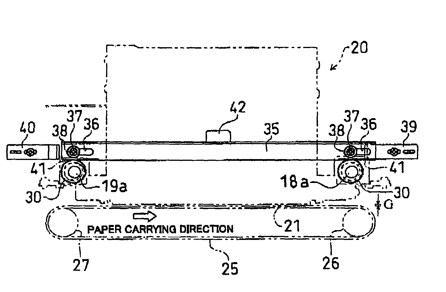
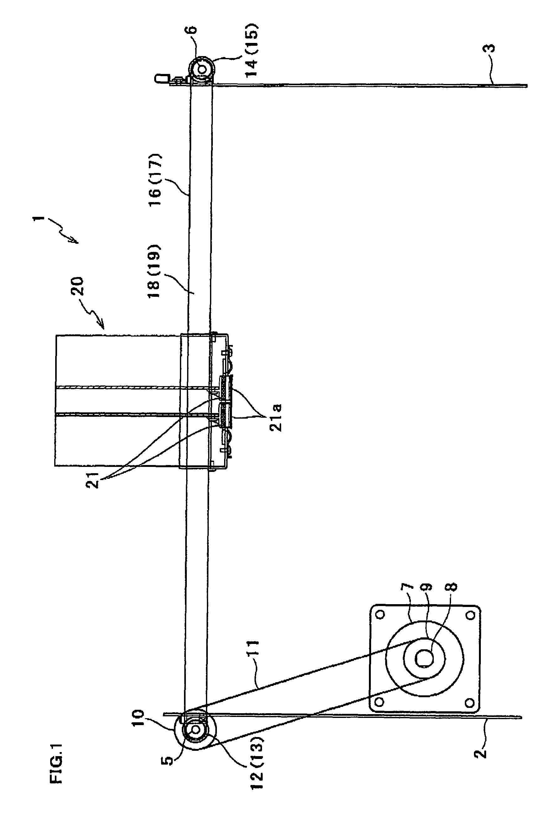
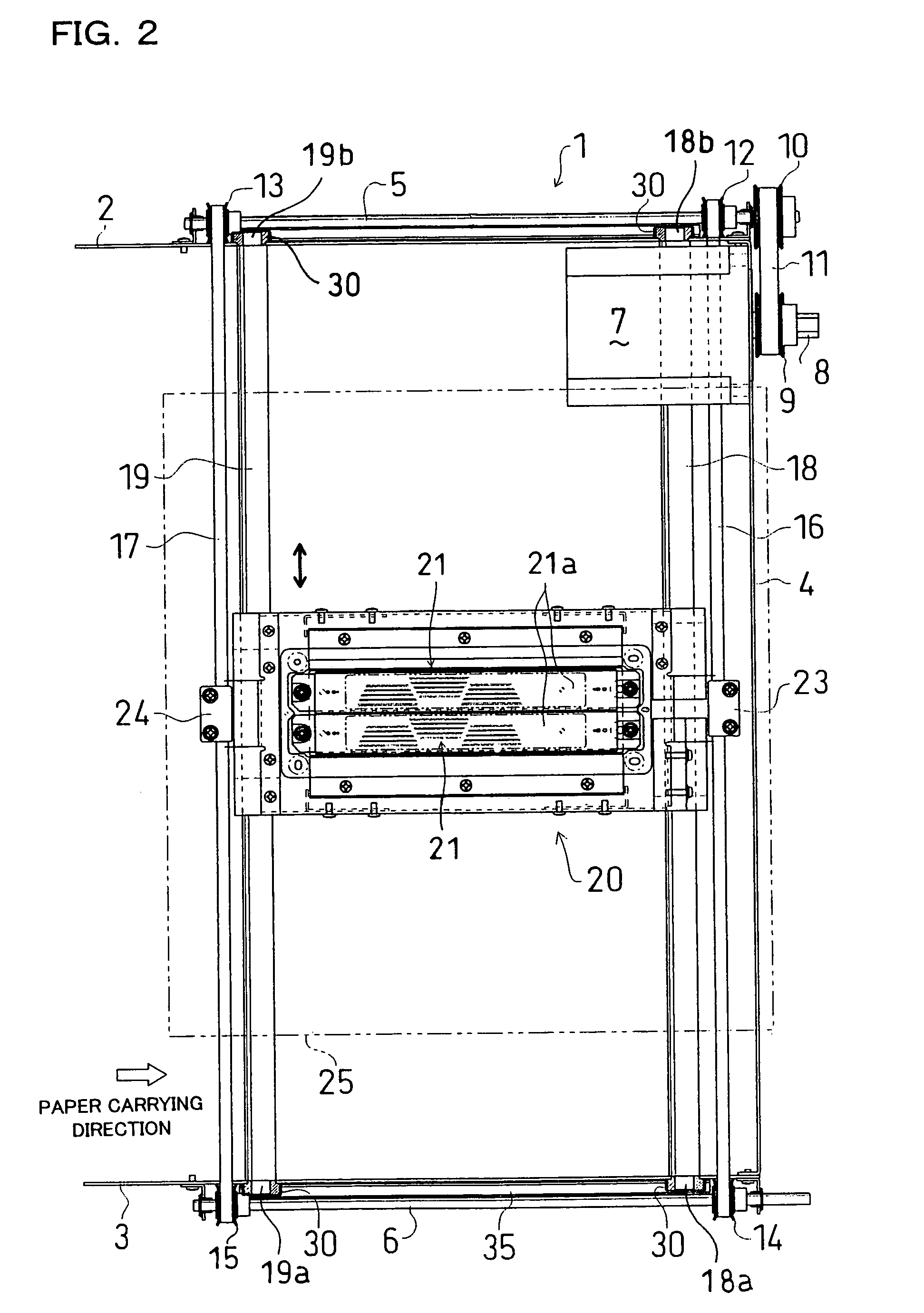
[0017]Referring first to FIGS. 1 and 2, an ink-jet printer 1 in accordance with an embodiment of the present invention is of a serial printing type having a carriage 20 that reciprocates transversely in FIG. 1. The carriage 20 provides a support for two ink-jet heads 21 such that their ink ejection surfaces 21a are horizontal. On the ink ejection surface 21a, a multiplicity of nozzles are arrayed in a matrix. The ink-jet head 21 is of a rectangular geometry whose longitudinal direction is orthogonal to the direction in which the carriage 20 moves. This ink-jet head 21 has a length of, e.g., about of 10 cm or longer and is elongated as compared with ones having in-line nozzles that are arrayed in one or two rows. In FIG. 1, a medium carrier is not shown such as a carrying belt 25 which will be described later.

[0018]As shown in FIG. 3, the carriage 20 has circular in section bores 20a and 20b disposed near its opposite ends along the longitudinal direction of the ink-jet heads 21. The...


PUM


Abstract

An ink-jet recording apparatus comprises an ink-jet head having an ink ejection surface on which a plurality of nozzles are arrayed; a medium carrier forming a carrying surface on which a record medium is carried; a carriage mounted with the ink-jet head such that the ink ejection surface confronts the carrying surface; a carriage drive mechanism including a plurality of parallel guide rods supporting the carriage and extending across the direction where the record medium is carried by the medium carrier, the carriage drive mechanism reciprocating the carriage along the guide rods; and a guide shift mechanism for shifting the plurality of guide rods in a direction where the gap between the ink ejection surface and the carrying surface varies.

Description

BACKGROUND OF THE INVENTION[0001]1. Field of the Invention[0002]The present invention relates to an ink-jet recording apparatus including an ink-jet head for ejecting ink droplets onto a record medium.[0003]2. Description of Related Art[0004]A plotter is known that performs recording with a pen that is moved by pulling via a belt a carriage mounted with the pen. Supporting the carriage by two guide rails is disclosed in Japanese Patent No. 2797637 as a technique for reciprocating the carriage in one direction in such a plotter. Application of this technique to a serial printing-type ink-jet printer results in a structure in which the carriage mounted with an ink-jet head is supported by two guide rods and simultaneously reciprocates along the guide rails. In this case, the distance from the ink ejection surface of the ink-jet head to the record medium carrying surface is invariable.[0005]However, a record medium for use in the ink-jet printer may have various thicknesses. Therefore,...

Claims


Application Information

Patent Timeline
IPC IPC(8): B41J25/308
CPCB41J25/308B41J25/3088
Inventor OKAMOTO, TSUGIO
Owner BROTHER KOGYO KK
Why Eureka
Try Eureka