Sculling boat assembly

a technology for sculling boats and parts, applied in the direction of vessel construction, marine propulsion, transportation and packaging, etc., can solve the problems and achieve the effect of relatively high cost of manufacture and tim

Inactive Publication Date: 2005-11-15
LIN ROGER
View PDF6 Cites 20 Cited by
  • Summary
  • Abstract
  • Description
  • Claims
  • Application Information

AI Technical Summary

Benefits of technology

[0005]In view of the description above, it is not difficult for us to find out that a manual-control small boat such as a sculling boat becomes users' favorite as the water sports and recreation industry is booming. Due to the structural design in the past, the cost of manufacture and time were relatively high, which is not definitely an economic arrangement. Therefore, the inventor

Problems solved by technology

Due to the structural design in the past, the cost of manufacture and ti

Method used


Image

  • Sculling boat assembly
  • Sculling boat assembly
  • Sculling boat assembly

Examples


Embodiment Construction

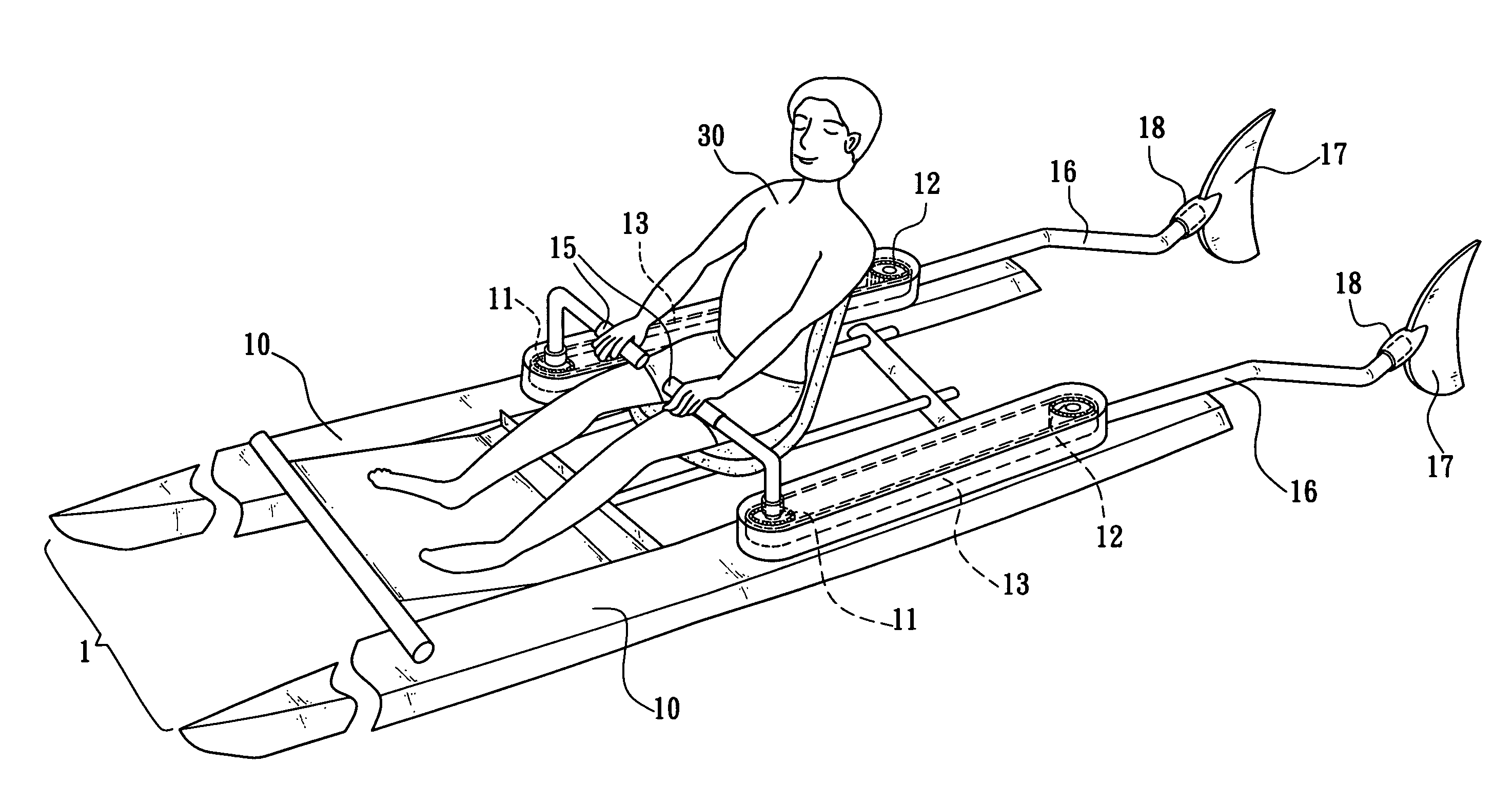
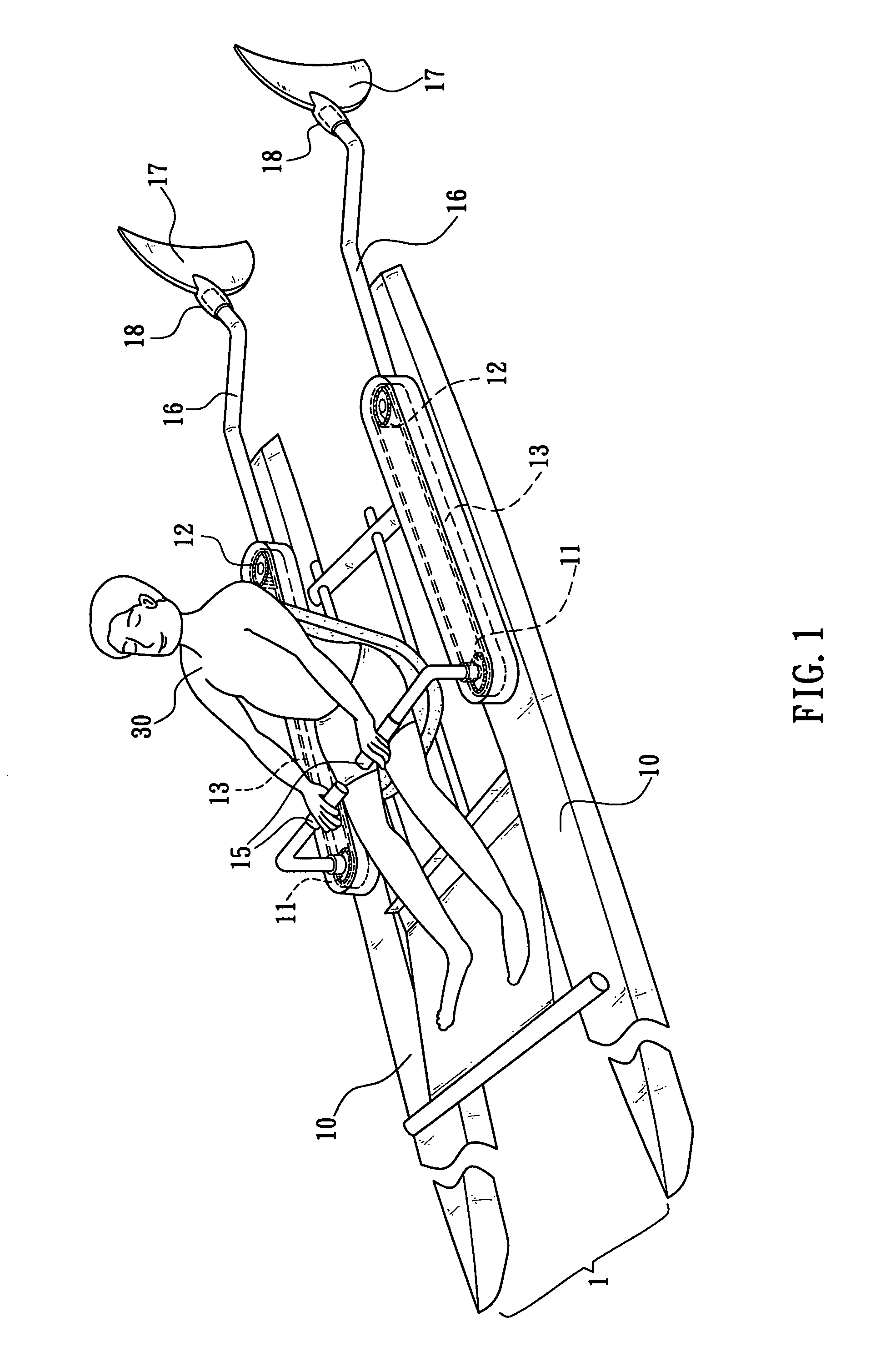
[0012]Referring to FIG. 1, a sculling boat assembly in accordance with a preferred embodiment of the present invention is illustrated. The sculling boat assembly comprises a boat body 1 made of two hulls 10 aligned in parallel with each other and having a predetermined distance apart, and the predetermined distance is provided for carrying a user 30; a first rotary device 11 and a second rotary device 12, being installed proximate to the middle section and the rear section of the two hulls 10 respectively, and both first and second rotary devices 11, 12 are gears adopted in this preferred embodiment; a transmission device 13 being coupled separately to the first rotary device 11 and the second rotary device 12, and the transmission device 13 is a chain adopted in this preferred embodiment; a handle 15, being disposed on the first rotary device 11 and respectively extended into the two hulls 19, and the handle 15 is provided for the user 30 to reciprocally move the handle 15 along a ...


PUM


Abstract

A sculling boat assembly is provided to control the traveling direction and drive a boat, and the sculling boat assembly installs a transmission mechanism on two hulls, connects an end of each transmission mechanism to a handle extended from the two hulls, connects another end of each transmission mechanism to a paddle rod extended from the tail of the boat, and connects an end of each paddle rod with an extension of a fin-shape member. Through the transmission of each paddle rod, a user applies a force onto each handle to drive the fin-shape member disposed on each paddle rod for the movements of pushing water outward and enclosing water inward, such that the water resistance is converted into a reaction by the soft and hard materials of the fin-shape member and its extension to drive the boat to move forward rapidly.

Description

FIELD OF THE INVENTION[0001]The present invention generally relates to a sculling boat assembly, and more particularly to a sculling boat assembly having a transmission mechanism installed on two hulls that are aligned in parallel with each other and maintain a predetermined distance apart. An end of each transmission mechanism is coupled with a handle extended from two hulls, and another end of each transmission mechanism is coupled to a paddle rod extended slightly downward from the tail of the boat. An end of each paddle rod is coupled with an extension disposed at an end of a fin-shape member. Therefore, a user just needs to apply a force onto each handle to move it reciprocally along a head and a tail of two hulls to drive the fin-shape member disposed on each paddle rod to create the movements of pushing water outward and enclosing water inward and drive the boat to move forward rapidly.BACKGROUND OF THE INVENTION[0002]As we know, boat is a sea transportation, which travels un...

Claims


Application Information

Patent Timeline
IPC IPC(8): B63H1/36B63H1/00B63H16/18
CPCB63H16/12B63H1/36
Inventor LIN, ROGER
Owner LIN ROGER
Why Eureka
Try Eureka