Color picture tube apparatus
a tube apparatus and tube tube technology, applied in the field of color picture tube apparatuses, can solve the problems of poor realizability and difficulty in optimally designing the beam through holes to satisfy all, and achieve the effect of facilitating the assembly of the electron gun
- Summary
- Abstract
- Description
- Claims
- Application Information
AI Technical Summary
Benefits of technology
Problems solved by technology
Method used
Image

Examples
embodiment 1
[0040]A color picture tube 1 according to the embodiments of the present invention will now be described in detail with reference to the drawings.
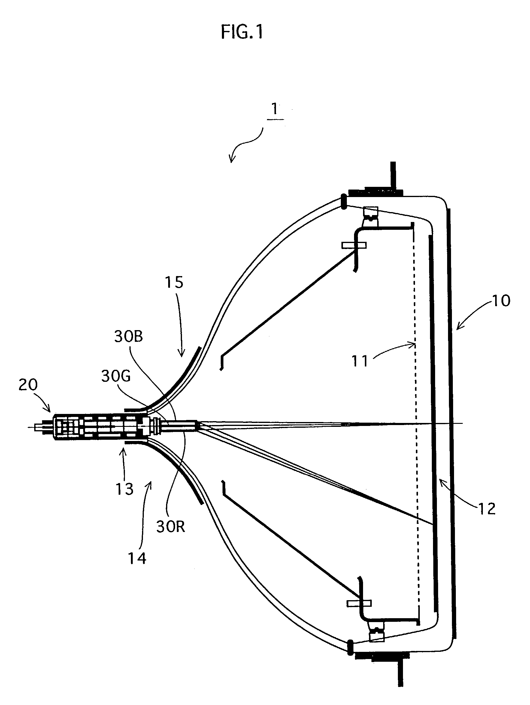
[0041]FIG. 1 is a cross-sectional view in a horizontal scan direction showing a structure of color picture tube 1.
[0042]As shown in this diagram, color picture tube 1 is structured from a picture tube 10 and an inline electron gun 20. Picture tube 10 includes a screen 10 that has R (red), G (green) and B (blue) phosphors applied in layers on a backside thereof, so as to face a shadow mask 11 that has a large number of electron beam through holes formed therein. Inline electron gun 20 is inserted from the base of a neck 13 of picture tube 10. Three electron beams 30R, 30G and 30B, corresponding to the colors RGB and emitted from inline electron gun 20, pass through a magnetic deflection field induced by a deflection coil 15 provided along the surface of an interface between neck 13 and a widening part 14 of a funnel. Electron beams 30R, 30G...
embodiment 2
[0068]An embodiment 2 of the present invention will now be described.
[0069]FIG. 10 is a plan view showing a structure of an inline electron gun according to the present embodiment, and FIGS. 11A and 11B show a related lens model.
[0070]A difference with embodiment 1 is that a pair of eave-shaped electrode plates 60 and 61 facing into and protruding toward the gap between focusing electrode 27 and final accelerating electrode 28 is also provided on field-correction electrode plate 27B.
[0071]According to this structure, as shown in FIGS. 11A and 11B, in addition to the lenses in FIG. 5, quadrupole lenses 66, 67 and 68 are generated that have, on the low-voltage side, greater divergent action horizontally (concave lens) and greater focusing action vertically (convex lens) than the main lenses.
[0072]Since these lenses allow for the horizontal focusing action to be weakened in the low-voltage area, which is an area greatly affected by spherical aberrations in the main lenses, it is possib...
embodiment 3
[0074]An embodiment 3 of the present invention will now be described.
[0075]FIG. 12 is a plan view showing a structure of an inline electron gun according to embodiment 3.
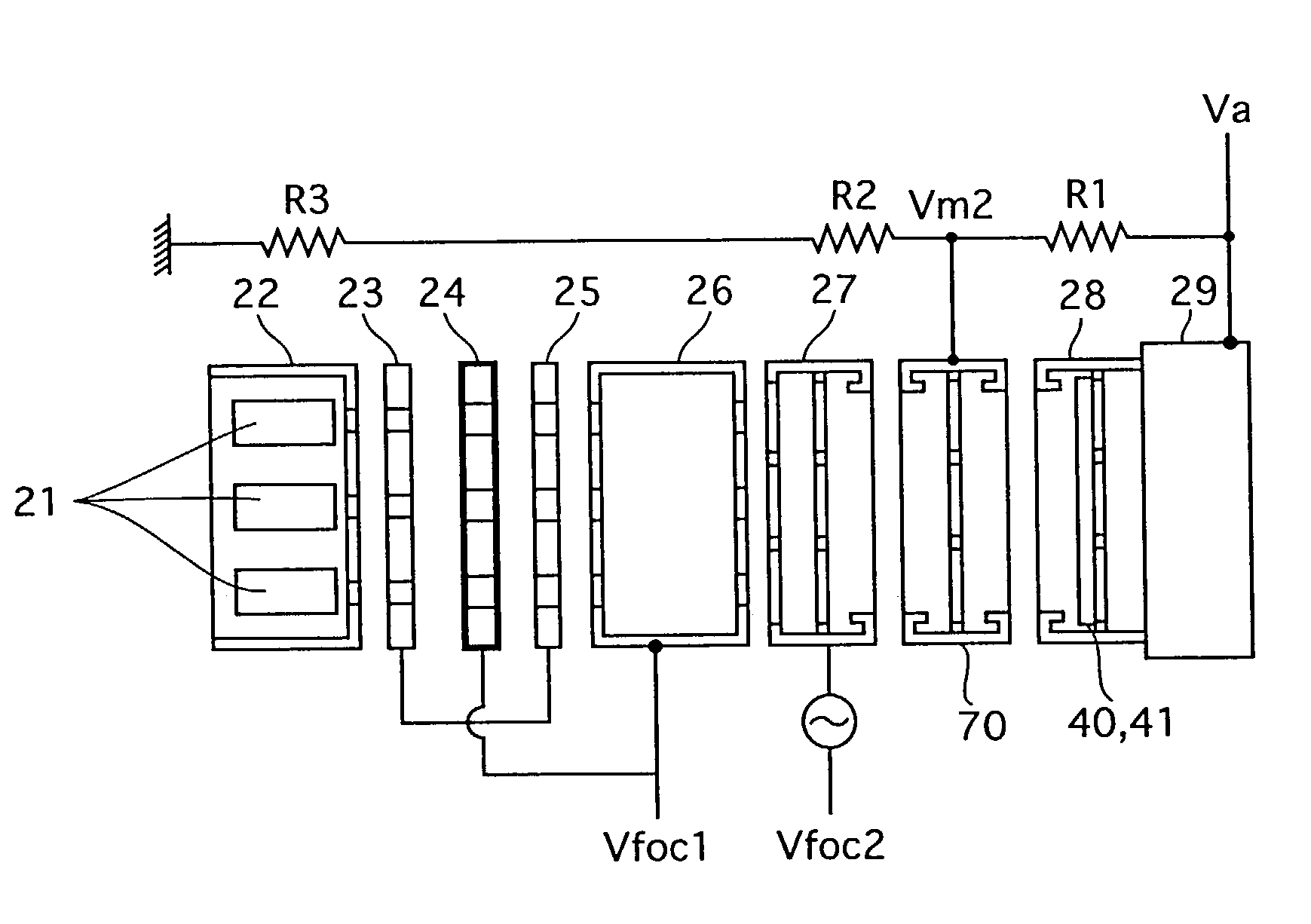
[0076]In the inline electron gun of the present embodiment, as shown in this diagram, protrusions 29A are formed on the shield cap of the inline electron gun of embodiment 1, so as to protrude into the final accelerating electrode, and a base 29B of protrusions 29A functions as a field-correction electrode plate. Eave-shaped electrode plates 40 and 41, as described above, are provided on base 29B.
[0077]In addition to above actions / effects, it is possible according to this structure to dispose the field-correction electrode plate within the final accelerating electrode when the shield cap is fitted to the final accelerating electrode, and thus facilitate the assembly of the electron gun.
[0078]Here, although embodiments 2 and 3 can be implemented independently, they may also be combined. Joint effects can thus be obta...
PUM
 Abstract
Description
Claims
Application Information
 - R&D Engineer
- R&D Manager
- IP Professional
- Industry Leading Data Capabilities
- Powerful AI technology
- Patent DNA Extraction
Browse by: Latest US Patents, China's latest patents, Technical Efficacy Thesaurus, Application Domain, Technology Topic.
© 2024 PatSnap. All rights reserved.Legal|Privacy policy|Modern Slavery Act Transparency Statement|Sitemap