Two-port non-reciprocal circuit device, composite electronic component, and communication apparatus

a non-reciprocal circuit and circuit technology, applied in waveguide devices, basic electric elements, electrical devices, etc., can solve the problems of unbalanced input and output terminals, increased size and cost of devices, and inability to connect to a balanced circuit, etc., to achieve excellent stability and load regulation, power load efficiency and output distortion

Active Publication Date: 2005-11-15
MURATA MFG CO LTD
View PDF3 Cites 6 Cited by
  • Summary
  • Abstract
  • Description
  • Claims
  • Application Information

AI Technical Summary

Benefits of technology

[0022]Also, a composite electronic component according to a preferred embodiment of the present invention includes the two-port non-reciprocal circuit device having the above-described characteristics and a power amplifier which is electrically connected to the two-port non-reciprocal circuit device, wherein a balanced output terminal of the power amplifier is electrically connected to the balanced input terminal of the two-port non-reciprocal circuit device. In this composite electronic component, a load impedance from the side of the output terminal of the power amplifier is constant regardless of the operating state of a subsequent-stage circuit or the operating environment. Therefore, the power load efficiency and output distortion characteristic of the power amplifier can be constantly maintained at the optimal state.
[0023]Further, a communication apparatus according to another preferred embodiment of the present invention includes the two-port non-reciprocal circuit device and the composite electronic component having the above-described characteristics. Accordingly, a compact communication apparatus having an excellent stable load regulation can be obtained.

Problems solved by technology

In the two-port non-reciprocal circuit device of the Patent Document 1, however, both input and output terminals are unbalanced terminals, and thus cannot be connected to a balanced circuit.
In this way, when the balun and the non-reciprocal circuit device are used together, the size and cost of the device increase, the structure is complicated, and reliability decreases.
Therefore, it causes imbalance between the two balanced output terminals.
As a result, undesired waves other than necessary signal waves pass through the non-reciprocal circuit device disadvantageously.

Method used


Image

  • Two-port non-reciprocal circuit device, composite electronic component, and communication apparatus
  • Two-port non-reciprocal circuit device, composite electronic component, and communication apparatus
  • Two-port non-reciprocal circuit device, composite electronic component, and communication apparatus

Examples


first preferred embodiment

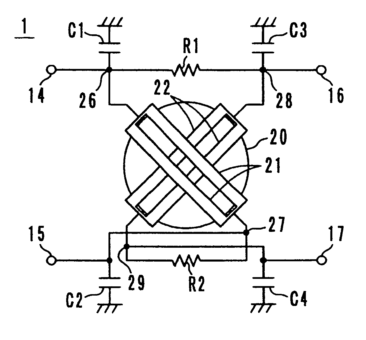
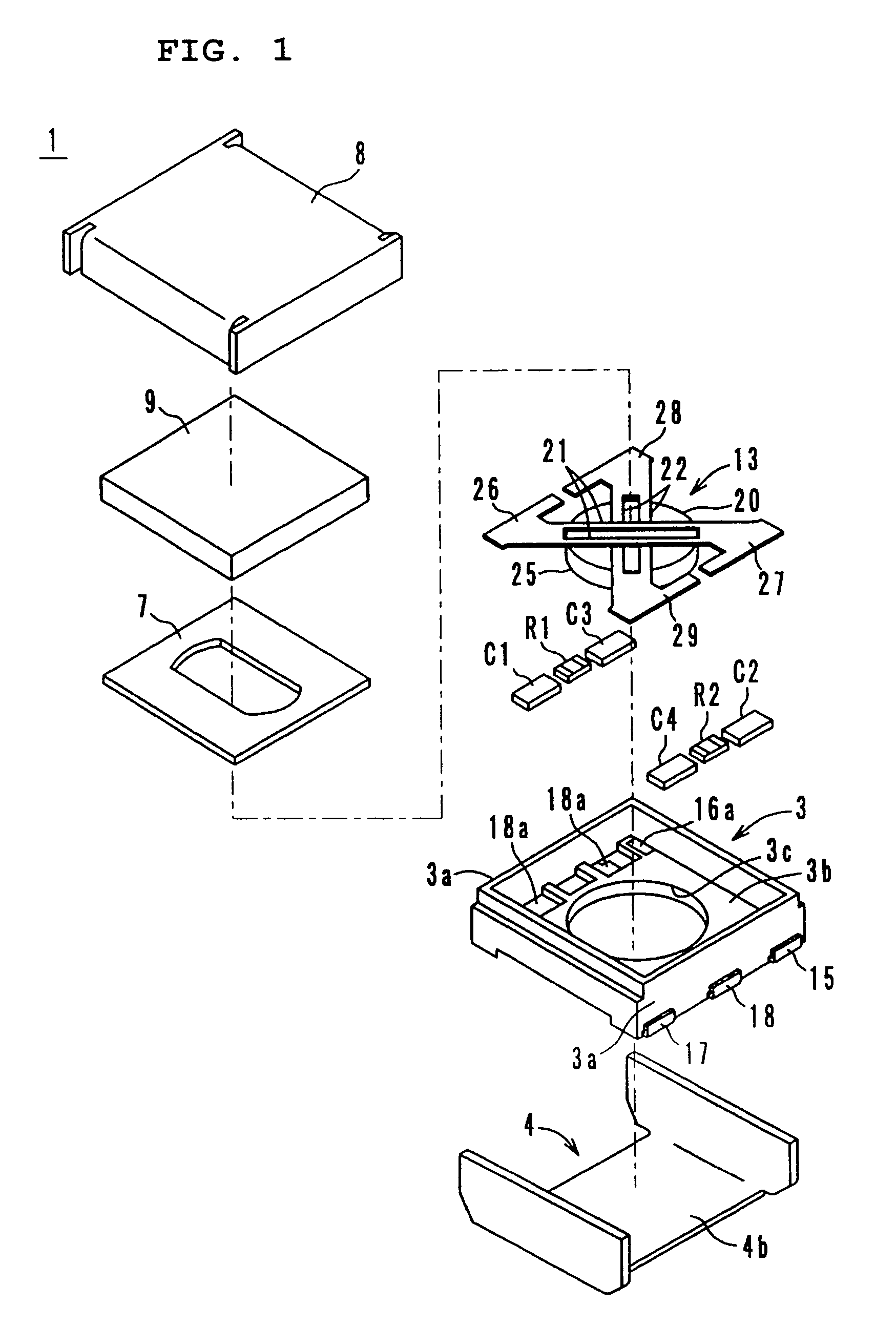
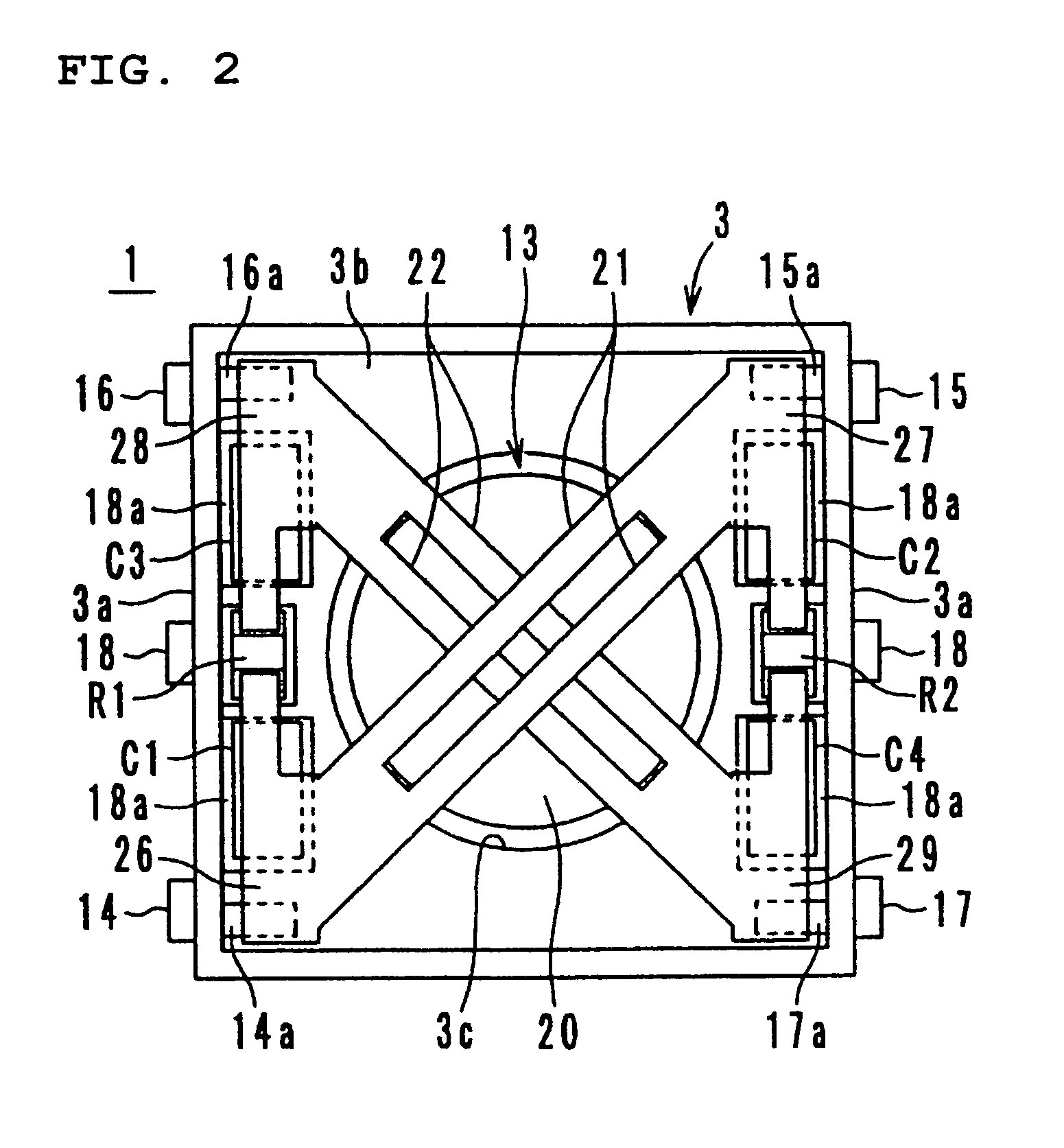
[0037]As shown in FIG. 1, a two-port isolator 1 according to a first preferred embodiment of the present invention preferably includes a metallic lower case 4, a resin terminal case 3, a central electrode assembly 13, a metallic upper case 8, a permanent magnet 9, an insulating member 7, resistors R1 and R2, and matching capacitors C1 to C4.

[0038]The metallic lower case 4 and the metallic upper case 8 are preferably made of a ferromagnetic material, such as soft iron, so as to form a magnetic circuit. The surface thereof is preferably Ag-plated or Cu-plated so as to improve an insertion loss characteristic. The insulating member 7 preferably includes a dielectric material, such as LCP (liquid crystal polymer), PPS, PBT, PEEK, or epoxy resin, or other suitable material.

[0039]In the central electrode assembly 13, a first central electrode 21 and a second central electrode 22 are arranged on the upper surface of a disc-shaped microwave ferrite member 20, such that the electrodes cross ...

second preferred embodiment

[0058]A two-port isolator 41 of a second preferred embodiment preferably includes a central electrode assembly 43 shown in FIG. 5.

[0059]The central electrode assembly 43 preferably includes a microwave ferrite member 44, which is preferably substantially parallelogram-shaped in a plan view, and central electrodes 45 and 46, which are conductive wires covered with an insulating material. The conductive wires are wound on the surface of the ferrite member 44 such that they cross each other at substantially right angles. More preferably, the shape of the ferrite member 44 is preferably substantially quadrangular (approximately square or approximately rectangle) or substantially rhombic. Alternatively, a substantially circular shape may be adopted.

[0060]As the conductive wires, copper wires or silver wires may be used. Alternatively, steel wires may be coated with gold, silver, or copper. The cross section of the conductive wire may be substantially circular or substantially rectangular...

fifth preferred embodiment

[0068]As shown in FIG. 8, a two-port isolator 71 preferably includes a metallic case having a metallic lower case 74 and a metallic upper case 78, a permanent magnet 79, a central electrode assembly 90 and a substantially rectangular laminated substrate 100 having terminator resistors R1 and R2 and matching capacitors C1 to C4.

[0069]In the central electrode assembly 90, two pairs of central electrodes 91 and 92 are arranged on the upper surface of a microwave ferrite member 93, which is preferably substantially rectangular-shaped when viewed in a plan view, such that the central electrodes 91 and 92 cross each other at substantially right angles and an insulating layer (not shown) is provided therebetween. In the fifth preferred embodiment, each of the central electrodes 91 and 92 includes two lines.

[0070]The central electrodes 91 and 92 may be bonded to the ferrite member 93 by using a copper foil, or may be provided by printing a conductive paste including Ag, Au, Ag—Pd, or Cu on ...


PUM


Abstract

In a two-port non-reciprocal circuit device, connecting portions of a first central electrode are electrically connected to first and second balanced input terminals, respectively. Likewise, connecting portions of a second central electrode are electrically connected to first and second balanced output terminals, respectively. First and second resistors are electrically connected between the first balanced input terminal and the first balanced output terminal and between the second balanced input terminal and the second balanced output terminal, respectively. First to fourth matching capacitors are electrically connected between the connecting portions of the first and second central electrodes and ground, respectively.

Description

BACKGROUND OF THE INVENTION[0001]1. Field of the Invention[0002]The present invention relates to a two-port non-reciprocal circuit device, such as an isolator used in a microwave band, a composite electronic component, and a communication apparatus.[0003]2. Description of the Related Art[0004]Two-port non-reciprocal circuit devices disclosed in U.S. Pat. No. 4,016,510 (Patent Document 1) and Japanese Unexamined Patent Application Publication No. 2002-299916 (Patent Document 2) are known. In the two-port non-reciprocal circuit device according to Patent Document 1, a first central electrode and a second central electrode are arranged on the upper surface of a ferrite member such that the electrodes cross each other and are electrically insulated from each other. One end of each of the first and second central electrodes is grounded, and the other ends thereof are electrically connected to an input terminal and an output terminal, respectively. Also, a resistor is electrically connect...

Claims


Application Information

Patent Timeline
Patent Type & Authority Patents(United States)
IPC IPC(8): H01P1/36H01P1/365H01P1/32
CPCH01P1/36
Inventor KAWANAMI, TAKASHI
Owner MURATA MFG CO LTD
Why Eureka
Try Eureka