Spinning reel with rear adjustable drag, adjustable handle length and universal pivot handle grip

Inactive Publication Date: 2005-11-22
W C BRADLEYZEBCO HLDG
View PDF19 Cites 6 Cited by
  • Summary
  • Abstract
  • Description
  • Claims
  • Application Information

AI Technical Summary

Benefits of technology

[0012]It is another object of the invention herein to provide a fishing reel having a handle arm of adjustable length wherein the adjustment may be made quickly

Problems solved by technology

Some fishermen prefer to use spinning reels for deep sea fishing; however, present deep sea spinning reels have several drawbacks.
Spinning reels traditionally have drag adjustments positioned on the front of the s

Method used


Image

  • Spinning reel with rear adjustable drag, adjustable handle length and universal pivot handle grip
  • Spinning reel with rear adjustable drag, adjustable handle length and universal pivot handle grip
  • Spinning reel with rear adjustable drag, adjustable handle length and universal pivot handle grip

Examples


Example

[0036]The same reference numerals refer to the same elements throughout the various figures.

DESCRIPTION OF THE PREFERRED EMBODIMENT

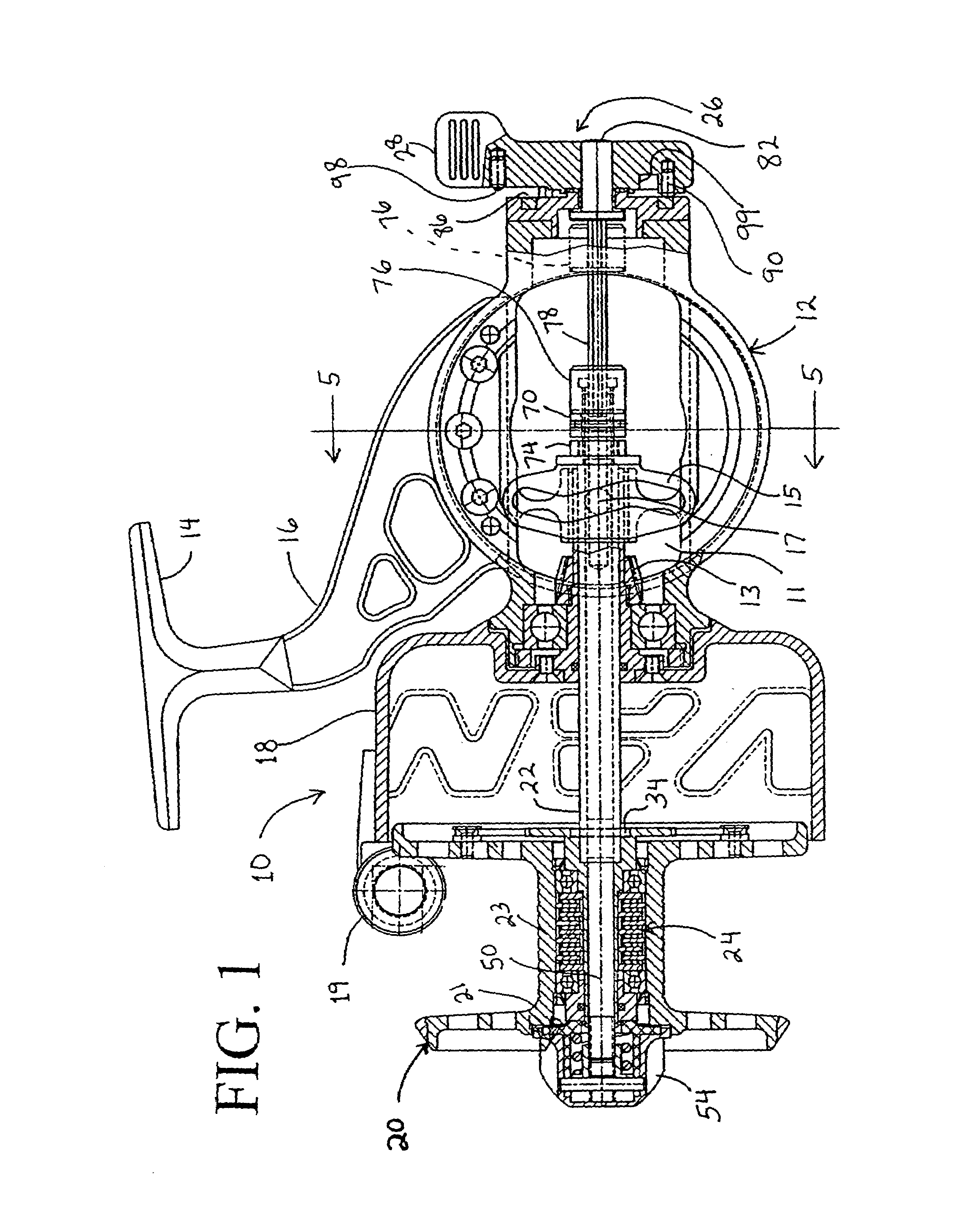
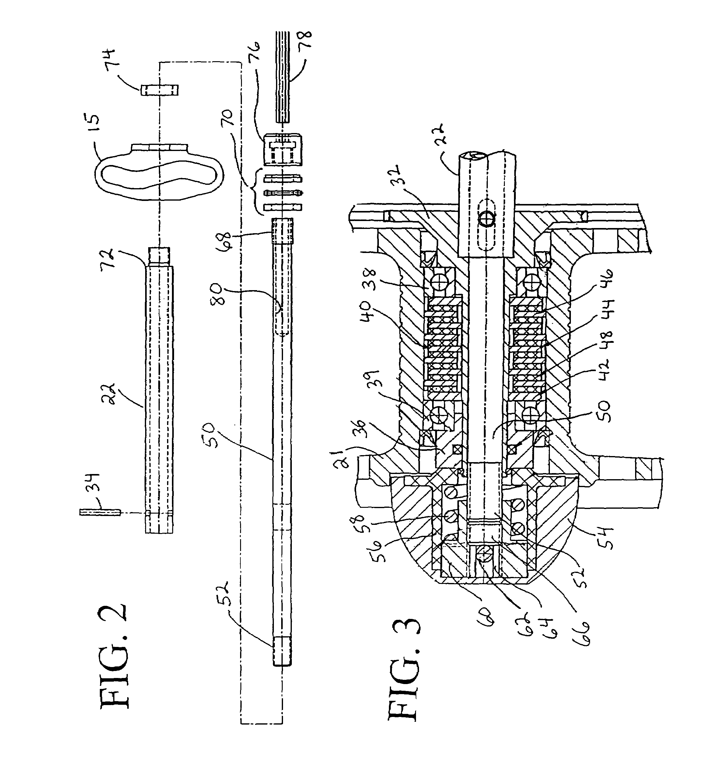
[0037]A spinning reel 10 according to the invention herein is illustrated in the various Figures. It generally comprises a reel body 12 having a foot 14 extending therefrom on a strut 16, the foot 14 being adapted for mounting the reel 10 to a fishing rod. The reel body 12 has a rotating flyer 18 mounted on the front thereof, and a spool assembly 20 mounted on a tubular main spool shaft 22 extending from the reel body.

[0038]The spool assembly partially contains a drag assembly generally indicated at 24. A drag adjustment mechanism 26 has its handle 28 positioned at the rear of the reel body 12.

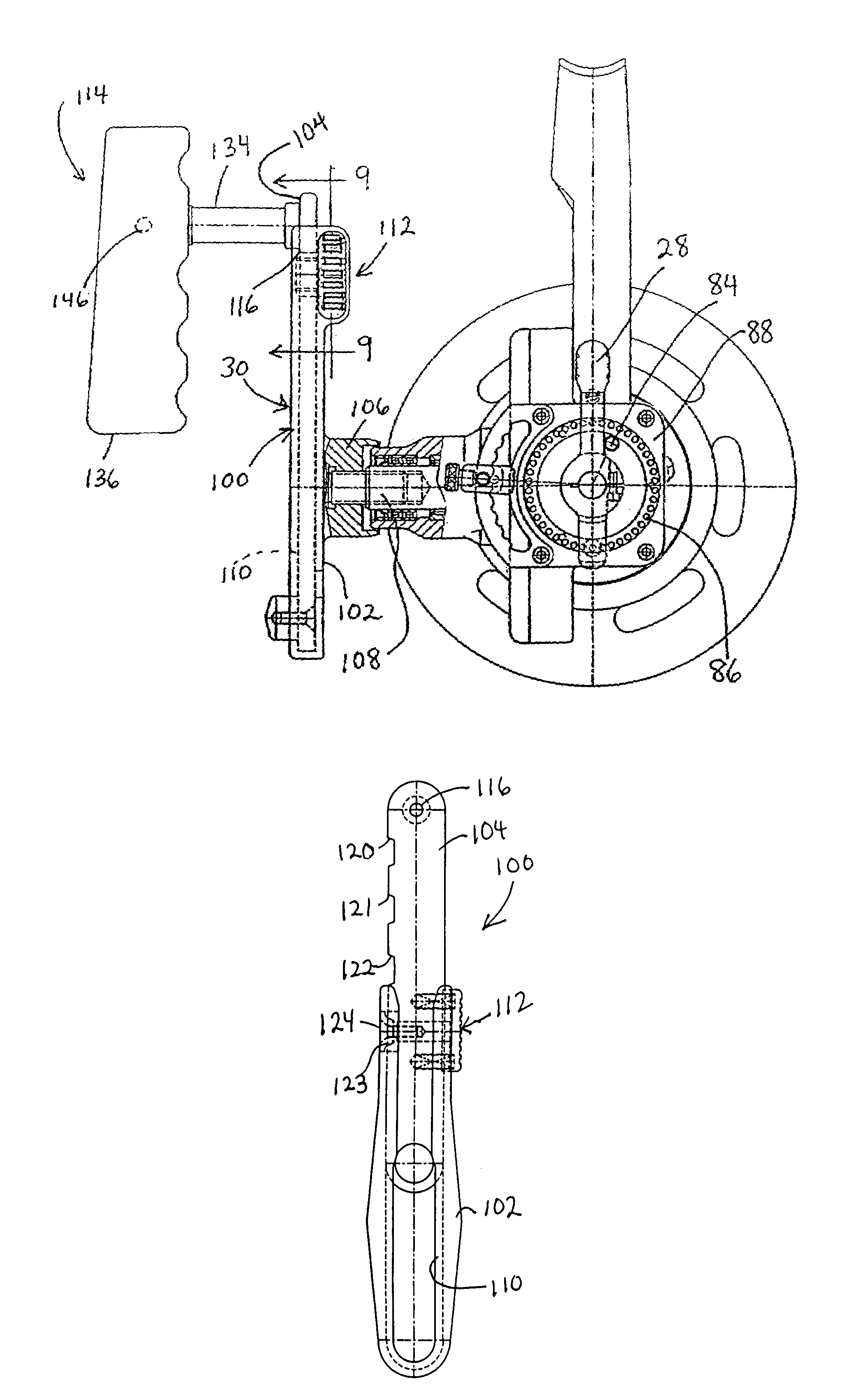
[0039]The spinning reel 10 further generally comprises a handle 30 including a handle arm 100 and a handle grip 114.

[0040]It will be understood that the reel body 12 contains a drive mechanism for rotating the flyer 18 and for reciprocating the spool assembly 20 in...


PUM


Abstract

A spinning reel has a drag assembly in its spool on one end of the reel body, and an adjustment knob for the drag assembly on another end of the reel body, where it is conveniently accessed during use of the reel. The reel has a handle arm with two slidably disposed handle arm portions, which are releasably secured together at selected positions to provide a variable length handle arm.

Description

FIELD OF THE INVENTION[0001]The invention here in relates to a spinning reel having a drag mechanism adjustable from the rear of the reel body, a handle arm of adjustable length, with the handle further providing a rotatable and pivotal grip.BACKGROUND OF THE INVENTION[0002]Deep sea fishing for large game fish, such as swordfish and tuna, is a demanding and rigorous sport that requires excellent fishing tackle. Some fishermen prefer to use spinning reels for deep sea fishing; however, present deep sea spinning reels have several drawbacks.[0003]The drag, or amount of frictional force the reel itself applies to the fishing line, must be set accurately and quickly. Spinning reels traditionally have drag adjustments positioned on the front of the spool, and it is highly difficult to reach around the reel and make an adjustment while fighting a fish. Yet, it is desirable to be able quickly set an initial drag for use following the initial strike, and then be able to adjust the drag duri...

Claims


Application Information

Patent Timeline
IPC IPC(8): A01K89/027A01K89/00
CPCA01K89/006A01K89/027Y10T74/20744A01K89/009A01K89/01A01K89/03G05G1/085
Inventor KOELEWYN, ROBERT W.LIU, DONALD C.
Owner W C BRADLEYZEBCO HLDG
Why Eureka
Try Eureka