Jack dolly with brake

a brake and jack technology, applied in the field of jack dollies, can solve the problems of jacks being easily transported over relatively long distances, jacks being susceptible to being stuck in small cavities, and the situation is further exacerbated, so as to achieve less effort and difficulty

Inactive Publication Date: 2005-11-22
GOLDIE LOWELL D
View PDF24 Cites 3 Cited by
  • Summary
  • Abstract
  • Description
  • Claims
  • Application Information

AI Technical Summary

Benefits of technology

[0009]The primary object of the present invention and advantages of the present invention is to provide a jack dolly onto which a hydraulic vehicle jack can be releasably secured and then transported, moved, or otherwise wheeled about with significantly less effort and difficulty than that required for transport of said jack.
[0010]A further object of the present invention to provide a low cost, easy to manufacture, and easy to market jack dolly for hydraulic vehicle jacks.
[0011]An even further object of the present invention is to provide an easy to use and versatile jack dolly for hydraulic automobile jacks.

Problems solved by technology

However, the features that allow the wheels of the jack to safely support the jack and a motor vehicle lifted by said jack prevent the jack from being easily transported over relatively long distances, such as across the floor of a shop, over a road or parking lot, or into a transport vehicle.
The metal construction and relatively small diameter of the wheels, for instance, makes the jack susceptible to becoming stuck in small cavities, depressions, or ruts in the shop floor, road, or parking lot or the movement of the jack is obstructed by small stones, pebbles, or uneven or raised floor, road or parking lot sections.
This situation is further exacerbated by the limited mobility of the jack due to the means of attaching the front and rear wheels as described earlier and the relatively heavy weight of a typical hydraulic automobile jack.
Additionally, the prior patents and commercial techniques do not suggest the present inventive combination of component elements arranged and configured as disclosed herein.

Method used


Image

  • Jack dolly with brake
  • Jack dolly with brake
  • Jack dolly with brake

Examples


Embodiment Construction

[0028]For purposes of describing the preferred embodiment, the terminology used in reference to the numbered components in the drawings is as follows:

[0029]

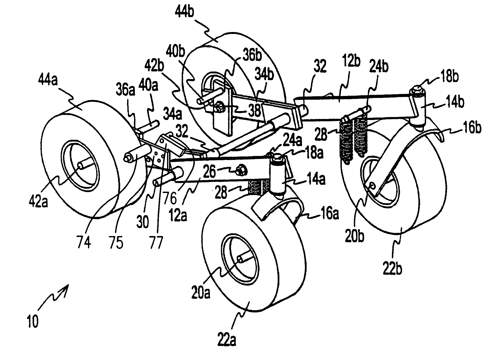
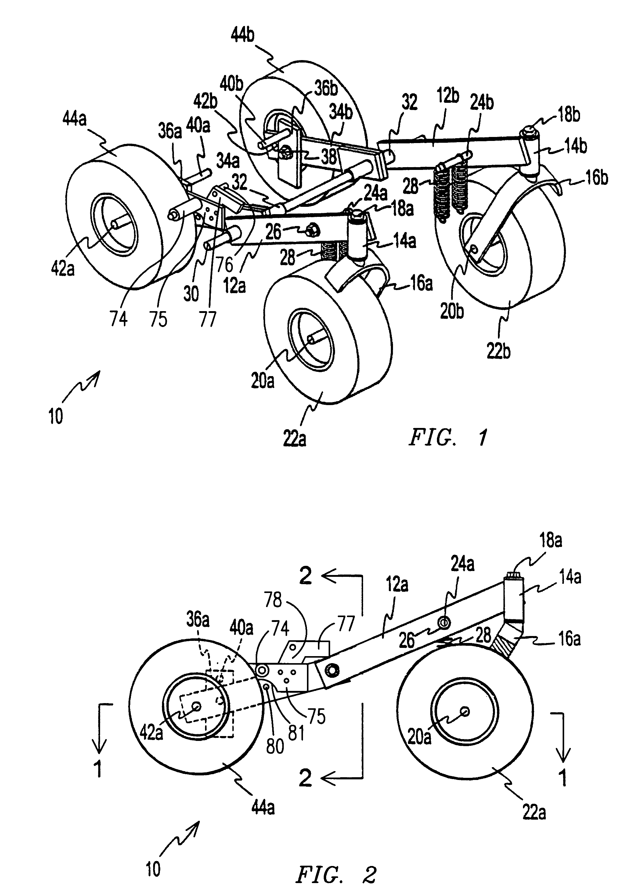
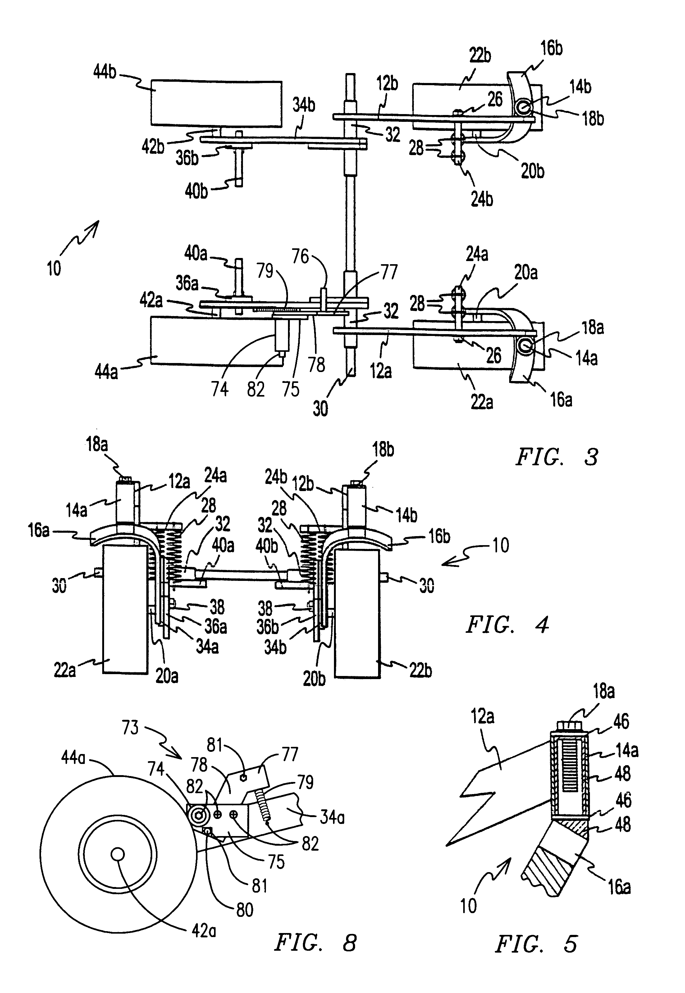
10.Jack Dolly12a, b.Front Arm Members14a, b.Collars16a, b.Forks18a, b.Bolts20a, b.Axles22a, b.Wheels24a, b.Rods26.Fastener28.Springs30.Rod32.Sleeve34a, b.Rear Arm Members36a, b.Plates38.Fastener40a, b.Rods42a, b.Axles44a, b.Wheels46.Bushing48.Shaft50.Hydraulic Automobile Jack54.Handle56.Rear Wheel58.Front Wheel60.Load Support Plate62.Aperture64.Rear Rod66.Middle Rod68.Front Rod70.Springs72.Springs73.Friction Brake74.Roller75.Roller Plate76.Brake Pedal77.Brake Arm78.Brake Plate79.Spring80.Locking Rod81.Notch82.Screw

[0030]Referring now to the drawings and, in particular, to FIG. 1 through FIG. 4 wherein there are illustrated a typical embodiment of the jack dolly 10, the jack dolly 10 is comprised of two elongate rectangular arm members 12a, b with cylindrical collars 14a, b that are attached to one end thereof. Wheel forks 16a, b ...


PUM


Abstract

A dolly (10) for transporting a jack (50) having front arm members (12a, b) attached to cooperating ends of rear arm members (34a, b) by a rod (30). The front arm members are mounted on wheels (22a, b) on the front arm member. The dolly is used to move vehicle jacks that have been modified to have an aperture (62) and mounting rods (64, 66, 68) attached to outside walls thereof. A friction brake (73) locks the rear wheel (44a) into place to prevent the jack from moving when in use. The modified jack is then aligned between the arm members of the dolly so that the rods on the front arm members of the dolly are inserted into the aperture on the jack. Springs (28, 70, 72) are secured between the dolly rods to the jack rods. The jack handle (54) can be manipulated to transport the jack to a desired location or secured to the hitch of a vehicle for towing.

Description

CROSS-REFERENCE TO RELATED APPLICATION[0001]This is a continuation-in-part of application Ser. No. 10 / 334,995, filed Dec. 30, 2002 U.S. Pat. No. 6,824,160.BACKGROUND OF THE INVENTION[0002]This invention relates to the field of jack dollies used for transporting hydraulic automobile jacks and more particularly, a jack dolly having four pivotally connected and cooperating arm members with at least four wheels for transporting a hydraulic automobile jack from a first location to a second location.[0003]Hydraulic automobile jacks are typically comprised of an elongate rectangular body with a pair of front wheels attached to a first end thereof and a pair of rear wheels attached to an opposing end thereof. An elongate cylindrical handle is attached to an internal hydraulic lift mechanism, which, upon pumping of the handle, raises a support plate from the rectangular body. A valve can be actuated to release the internal pressure generated by the pumping of the handle to lower the support ...

Claims


Application Information

Patent Timeline
Patent Type & Authority Patents(United States)
IPC IPC(8): B25H5/00B62B3/10B66F5/00
CPCB25H5/00B62B3/10B66F5/00
Inventor GOLDIE, LOWELL D.
Owner GOLDIE LOWELL D
Why Eureka
Try Eureka