Variable power optical system, imaging lens device and digital apparatus

a technology of optical system and lens device, applied in the field of zoom optical system, can solve the problems of increasing production cost, limited object to be photographed, and difficulty in molding the image-side lens surface, and achieve the effect of less difficulty, sufficient miniaturization, and same skill level

Inactive Publication Date: 2010-07-20
KONICA MINOLTA OPTO
View PDF22 Cites 4 Cited by
  • Summary
  • Abstract
  • Description
  • Claims
  • Application Information

AI Technical Summary

Benefits of technology

[0009]In view of the above conventional disadvantages, it is an object of the present invention to provide a zoom optical system, an imaging lens device, and a digital apparatus having lens elements in a first lens group produced with less difficulty i.e. with substantially the same skill level as the conventional arrangement, with sufficient miniaturization.

Problems solved by technology

Since the magnification of the single focus optical system is substantially equivalent to visual magnification, an object to be photographed is limited to the one located near a photographer.
In the zoom optical system, since the curvature of the image-side lens surface closest to the object side is large, it is difficult to produce the image-side lens surface by molding.
It is required to produce a so-called composite aspherical lens element by coating a resin on a spherical lens element, which may increase the production cost.
Also, since production error sensitivity is high with respect to the lens elements in both of the first lens group and the second lens group, an adjustment operation is required at the time of assembling the lens elements, which may further increase the production cost.
The optical system disclosed in patent document 2, however, uses three lens elements in each of the first lens group and the second lens group, which is far from sufficient miniaturization.
However, since impact resistance required in a mobile terminal is significantly large, it is difficult to employ a collapsible structure itself.
Consequently, the entire optical length of the optical system in a use state may be too large for a mobile terminal.
As a result, the curvature of the lens elements in the first lens group may be unduly increased, which may increase the expansion ratio of the lens elements.
Thus, it may be difficult to produce a zoom optical system or measure a surface configuration of lens elements.

Method used


Image

  • Variable power optical system, imaging lens device and digital apparatus
  • Variable power optical system, imaging lens device and digital apparatus
  • Variable power optical system, imaging lens device and digital apparatus

Examples


example 1

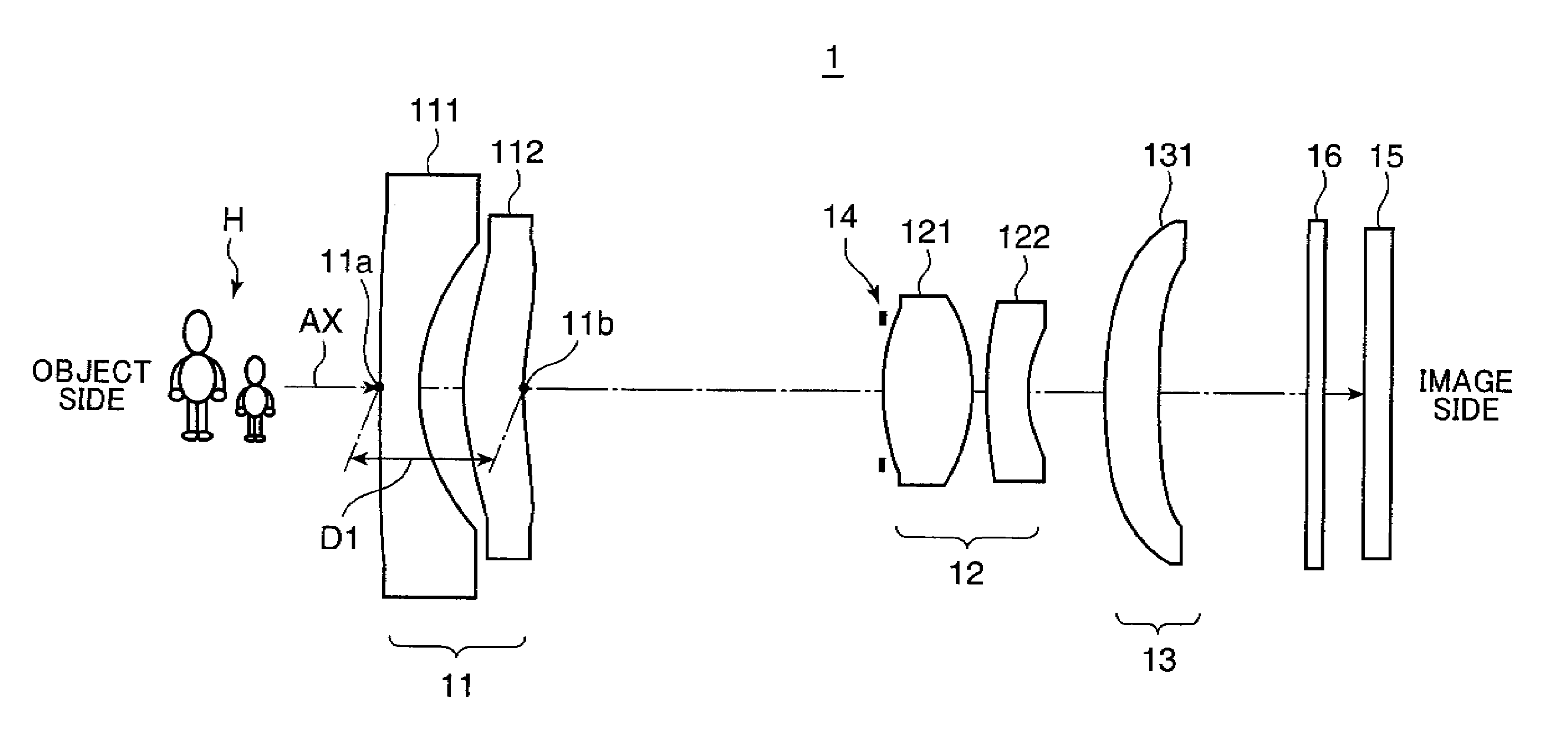
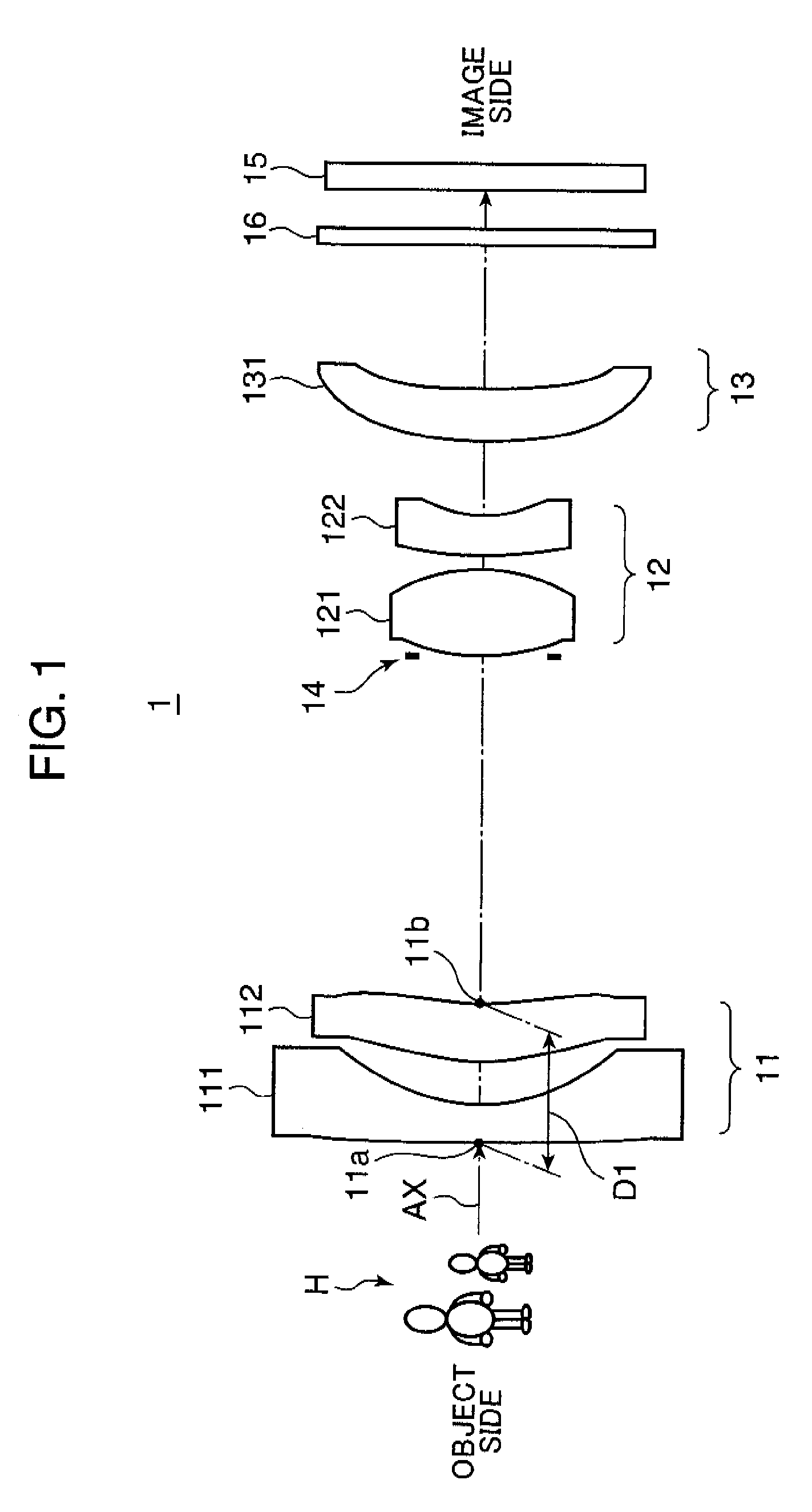
[0160]FIG. 6 is a cross-sectional view (i.e. an optical path diagram), taken along the optical axis (AX), showing an arrangement of lens groups in a zoom optical system 1A in Example 1. The optical path diagrams in FIG. 6, and FIGS. 7 through 13 to be described later each shows a lens arrangement at the wide angle end (W). Throughout Example 1, and Examples 2 through 8 to be described later, the lens groups include, in this order from the object side in the drawings (i.e. from the left side in FIG. 6), a first lens group (Gr1) having a negative optical power as a whole, a second lens group (Gr2) having a positive optical power, and a third lens group (Gr3) having a positive or negative optical power, except for Example 8. In other words, the lens arrangement is a negative dominant arrangement, in which the first lens group (Gr1) closest to the object side has a negative optical power.

[0161]The zoom optical system 1A in Example 1 shown in FIG. 6 has the following lens arrangement in ...

example 2

[0181]FIG. 7 is a cross-sectional view, taken along the optical axis (AX), showing an arrangement of lens groups in a zoom optical system 1B in Example 2. The zoom optical system 1B in Example 2 includes, in the order from the object side, a first lens group (Gr1) having a negative optical power as a whole, an aperture stop (ST), a second lens group (Gr2) having a positive optical power as a whole, and a third lens group (Gr3) having a positive optical power. More specifically, the first lens group (Gr1) is constituted of a biconcave negative lens element (L1) and a positive meniscus lens element (L2) convex to the object side in this order from the object side. The second lens group (Gr2) is constituted of a biconvex positive lens element (L3) and a negative meniscus lens element (L4) convex to the object side in this order from the object side. The third lens group (Gr3) is constituted of a positive meniscus lens element (L5) convex to the object side.

[0182]In the zoom optical sys...

example 3

[0186]FIG. 8 is a cross-sectional view, taken along the optical axis (AX), showing an arrangement of lens groups in a zoom optical system 1C in Example 3. The zoom optical system 1C in Example 3 includes, in the order from the object side, a first lens group (Gr1) having a negative optical power as a whole, an aperture stop (ST) arranged on the object side of a second lens group (Gr2), the second lens group (Gr2) having a positive optical power as a whole, and a third lens group (Gr3) having a positive optical power. More specifically, the first lens group (Gr1) is constituted of a biconcave negative lens element (L1) and a positive meniscus lens element (L2) convex to the object side in this order from the object side. The second lens group (Gr2) is constituted of a biconvex positive lens element (L3) and a negative meniscus lens element (L4) convex to the object side in this order from the object side. The third lens group (Gr3) is constituted of a positive meniscus lens element (...


PUM


Abstract

There is provided a zoom optical system having lens elements produced with less difficulty i.e. with substantially the same skill level as the conventional arrangement, with sufficient miniaturization. The zoom optical system includes a first lens group having a negative optical power, and a second lens group having a positive optical power in the order from the object side, the distance between the first lens group and the second lens group being decreased in zooming from a wide angle end to a telephoto end. The first lens group is constituted of a negative lens element and a positive meniscus lens element. The second lens group is constituted of a biconvex positive lens element and a negative meniscus lens element. Assuming that D1 represents a thickness of the first lens group on the optical axis AX from a forwardmost lens surface to a rearmost lens surface, fw represents a composite focal length of the entirety of the optical system at the wide angle end, and f2 represents a composite focal length of the second lens group, the zoom optical system satisfies the following relation:0.5<D1 / fw<0.80.7<f2 / fw<2.0

Description

RELATED APPLICATIONS[0001]This application is a National Stage of International Application No. PCT / JP2006 / 320853, filed Oct. 19, 2006, which is based on Japanese Patent Application No. 2005-310418, the entire contents of which is incorporated herein by reference.TECHNICAL FIELD[0002]The present invention relates to a zoom optical system constituted of lens groups and adapted to zoom by changing the distance between the lens groups in the optical axis direction, an imaging lens device incorporated with the zoom optical system, and a digital apparatus loaded with the imaging lens device, and more particularly to a zoom optical system or a like device suitable for miniaturization.BACKGROUND ART[0003]In recent years, mobile phones or PDAs (Personal Digital Assistants) have been widespread. Also, the specifications in which a compact digital still camera unit or a compact digital video unit is incorporated in the mobile phone or the PDA have been generalized. In a digital apparatus such...

Claims


Application Information

Patent Timeline
Patent Type & Authority Patents(United States)
IPC IPC(8): G02B15/14
CPCG02B13/22G02B15/177G02B15/143507
Inventor MATSUSAKA, KEIJI
Owner KONICA MINOLTA OPTO
Why Eureka
Try Eureka