Weather strip for a vehicle door

a technology for weather strips and doors, applied in the direction of doors, roofs, transportation and packaging, etc., to achieve the effects of preventing the rattling of the main body portion, improving the efficiency of the assembling operation, and outstanding assembling operation

Inactive Publication Date: 2005-11-22
TOKAI KOGYO CO LTD
View PDF10 Cites 82 Cited by
  • Summary
  • Abstract
  • Description
  • Claims
  • Application Information

AI Technical Summary

Benefits of technology

[0037]Accordingly, the lip-shaped upper and lower pressing forces are projectingly provided on the groove wall surface of the insertion groove on the exterior side wall portion side of the main body portion, and the lip-shaped pressing pieces are not provided on the groove wall surface of the insertion groove on the interior side wall portion side of the main body portion. Therefore, the attachment of the door trim in a substantially horizontal state is not affected by the elastic deformation of the pressing pieces. Hence, there is a rigid feel, and the efficiency in the assembling operation is outstanding.
[0038]In addition, by vir

Problems solved by technology

However, unlike that case, the resilient retainer is formed integrally with the main body portion, so that t

Method used


Image

  • Weather strip for a vehicle door
  • Weather strip for a vehicle door
  • Weather strip for a vehicle door

Examples


first embodiment

(First Embodiment)

[0051]Referring to FIGS. 1 to 6, a description will be given of a first embodiment of the invention.

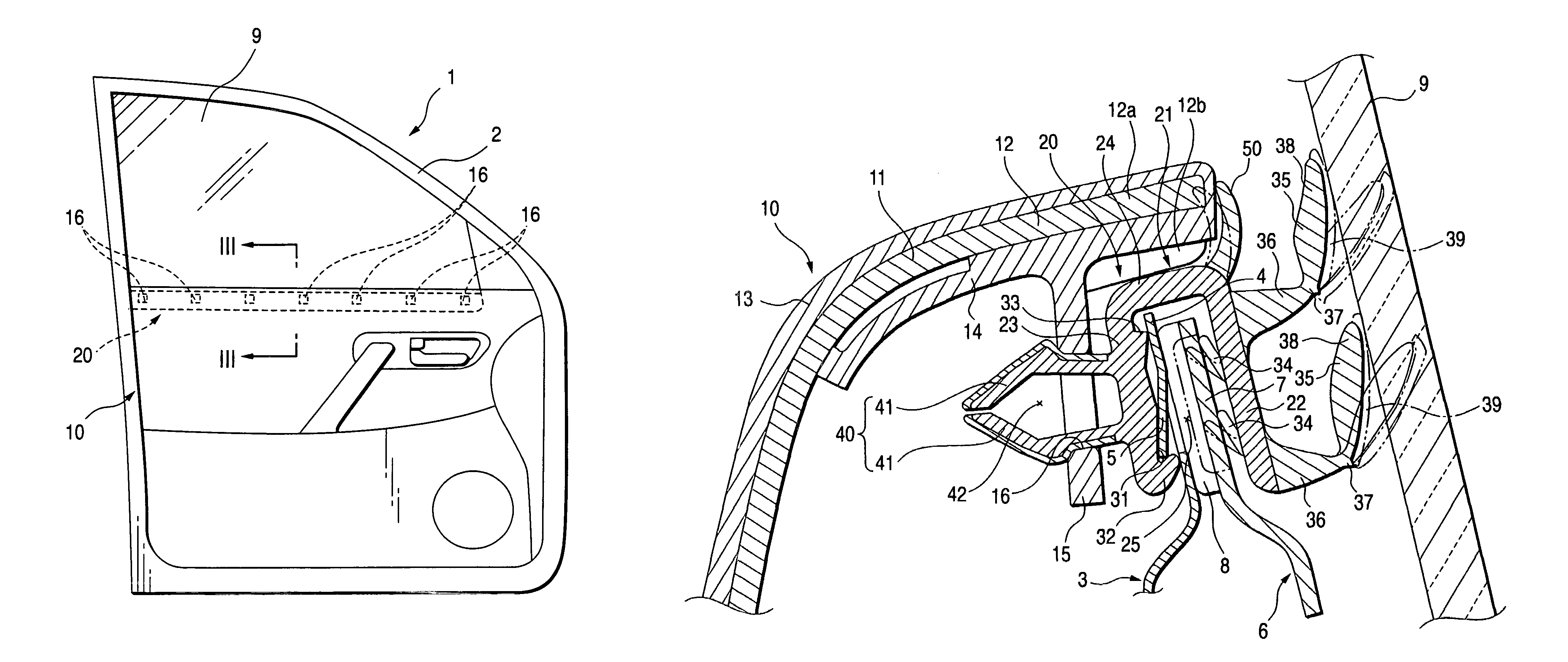
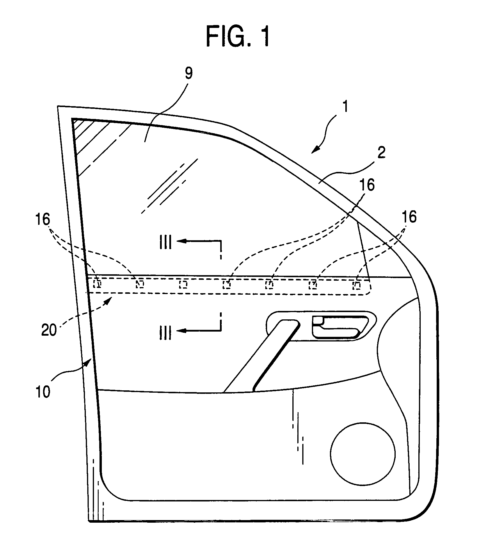
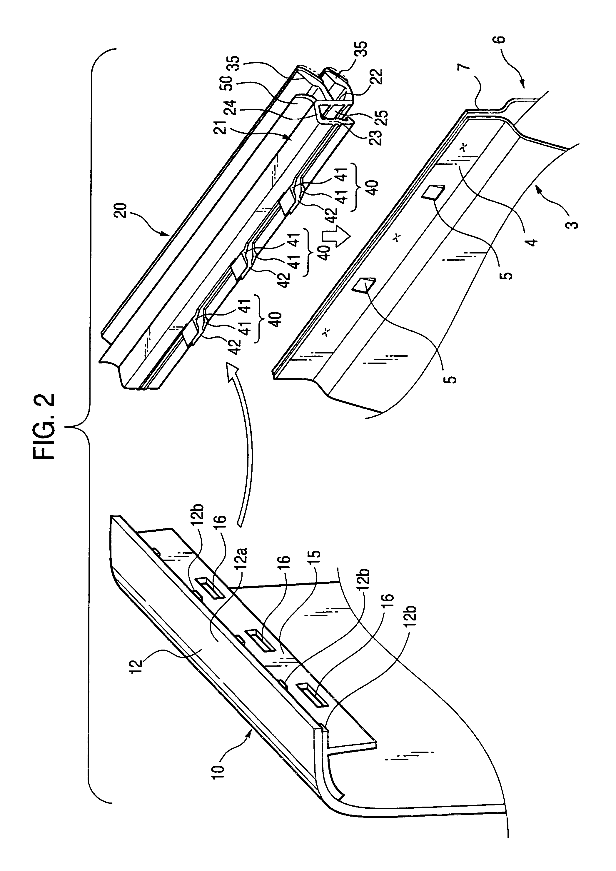
[0052]FIG. 1 is a front elevational view illustrating from the interior side a vehicle door fitted to a side portion of a vehicle. FIG. 2 is a perspective view illustrating a state before a door inner panel, a door trim, and a weather strip are assembled to each other. FIG. 3 is a sectional view taken along line III—III of FIG. 1. FIG. 4 is a cross-sectional view illustrating the weather strip which is in a free state before fitting. FIG. 5 is a perspective view illustrating the weather strip. FIG. 6 is a perspective view illustrating an extrusion molding before forming the weather strip.

[0053]As shown in FIGS. 1 to 3, a window frame 2 for constituting a window opening portion is formed at upper portions of a door inner panel 3 and a door outer panel (not shown) of a vehicle door 1, which is fitted to a side portion of the vehicle.

[0054]In addition, a lifting / lowerin...

second embodiment

(Second Embodiment)

[0108]Next, a description will be given of a second embodiment of the invention with reference to FIGS. 7 and 8.

[0109]FIG. 7 is a perspective view illustrating a state before the door inner panel, the door trim, and the weather strip in accordance with a second embodiment of the invention are assembled to each other. FIG. 8 is a cross-sectional view illustrating a state in which the door inner panel, the door trim, and the weather strip have been assembled to each other.

[0110]As shown in FIGS. 7 and 8, in this second embodiment, a plurality of downwardly oriented attaching portions 115 are formed at predetermined intervals on a longitudinal lower surface of the upper portion 12 of the door trim 10. The plurality of downwardly oriented attaching portions 115 are formed by groove portions or recessed portions.

[0111]In this second embodiment, the downwardly oriented attaching portion 115 has an upwardly projecting portion 115a and a downwardly projecting portion 115b...

third embodiment

(Third Embodiment)

[0119]Next, a description will be given of a third embodiment of the invention with reference to FIGS. 9 and 10.

[0120]FIG. 9 is a perspective view illustrating a state before component parts for resilient retainers are secured to the main body portion of the weather strip. FIG. 10 is a perspective view illustrating a state in which the component parts for resilient retainers are secured to the main body portion of the weather strip to construct the weather strip.

[0121]As shown in FIGS. 9 and 10, in this third embodiment, a plurality of longitudinally short resilient retainer component parts 240A are formed separately from the main body portion 21 of the weather strip 20. As the plurality of resilient retainer component parts 240A are secured at a predetermined heightwise position of the interior side wall portion 23 of the main body portion 21 of the weather strip 20 by an adhesive agent at predetermined intervals in the longitudinal direction thereof, resilient re...


PUM


Abstract

A weather strip for a vehicle door for being fitted to an upper edge flange of a door inner panel forming a window opening edge of the vehicle door having a lifting/lowering window pane. The weather strip includes: a main body portion having an insertion groove to be fitted to the upper edge flange; a seal lip portion projecting from the main body portion to be in resilient contact with the lifting/lowering window pane; and a resilient retainer to be resiliently engaged with a door trim. The main body portion includes a fixing portion to be engaged with the upper edge flange. The resilient retainer is projected outward from the main body portion in a substantially horizontal direction and perpendicular to an attaching portion provided at an upper portion of the door trim, when the insertion groove is fitted to the upper edge flange substantially.

Description

BACKGROUND OF THE INVENTION[0001]1. Field of the Invention[0002]The present invention relates to a vehicle interior side weather strip (which is sometimes called an inner belt molding) which is installed along a lower end portion of a window opening portion of a vehicle door.[0003]2. Background Art[0004]Among vehicle doors (mainly side doors), one is known in which a lifting / lowering window pane (side door glass) disposed liftably in the door is disposed in such a manner as to be capable of being lifted or lowered along a lifting path the upper side of which is inclined toward the interior side more than the lower side thereof, i.e., which is inclined in such a manner as to be displaced toward the interior side as it is headed toward the upper side.[0005]In addition, a vehicle interior side weather strip is installed by being fitted over the upper edge flange of a door inner panel, which forms a vehicle interior side window opening edge of the vehicle door.[0006]Namely, the weather ...

Claims


Application Information

Patent Timeline
IPC IPC(8): B60J10/02B60J10/04
CPCB60J10/0065B60J10/041B60R13/0206B60R13/0237B60R13/025B60R2013/0287B60J10/32B60J10/75
Inventor MATSUMOTO, ATSUSHINAGAI, KATSUAKITAMAOKI, AKIHIROHISADA, YUJI
Owner TOKAI KOGYO CO LTD
Why Eureka
Try Eureka