Clip-chain module of rolling unit

a technology of clip-chain module and rolling unit, which is applied in the direction of bearings, shafts and bearings, bearings, etc., can solve the problems of affecting the rolling the production cost is relatively increased, etc., and achieves the effects of enhancing the competitiveness of the product, reducing the friction of the rolling element, and improving the difficulty of the process

Inactive Publication Date: 2005-11-22
HIWIN TECH
View PDF2 Cites 17 Cited by
  • Summary
  • Abstract
  • Description
  • Claims
  • Application Information

AI Technical Summary

Benefits of technology

[0007]In accordance with one aspect of the present invention is to provide a clip-chain module of rolling unit, which includes the spacer, the end-part and the link-belt. The characteristic of the clip-chain module of rolling unit was made up of one or upward half clip-chains thereby can reduce the friction of the rolling element and improve the difficulty of the process. Therefore, this invention can enhance the competitiveness of this product.

Problems solved by technology

It is time-consuming to assemble this rolling unit by alternatively inserting the rolling element and single receiver in the slide block, furthermore, the receivers and the rolling elements are coupled with each other closely, such will cause interference in the rolling of the rolling element.
The method of making this kind of receiver 31 is by putting the rolling elements in a mould and made by plastic ejection moulding, the material and the ejection moulding machine should be high quality, thus the production cost is relatively increased.
Furthermore, due to the special manufacturing method, the receivers and the rolling elements are coupled with each other closely, such will interfere in the rolling of the rolling element.

Method used


Image

  • Clip-chain module of rolling unit
  • Clip-chain module of rolling unit
  • Clip-chain module of rolling unit

Examples


first embodiment

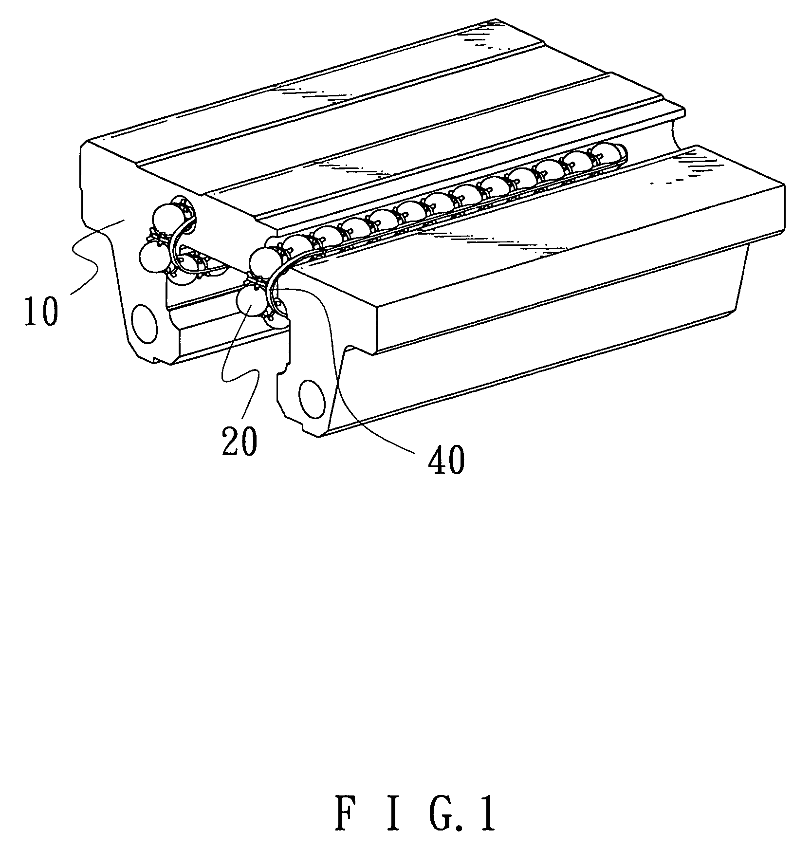
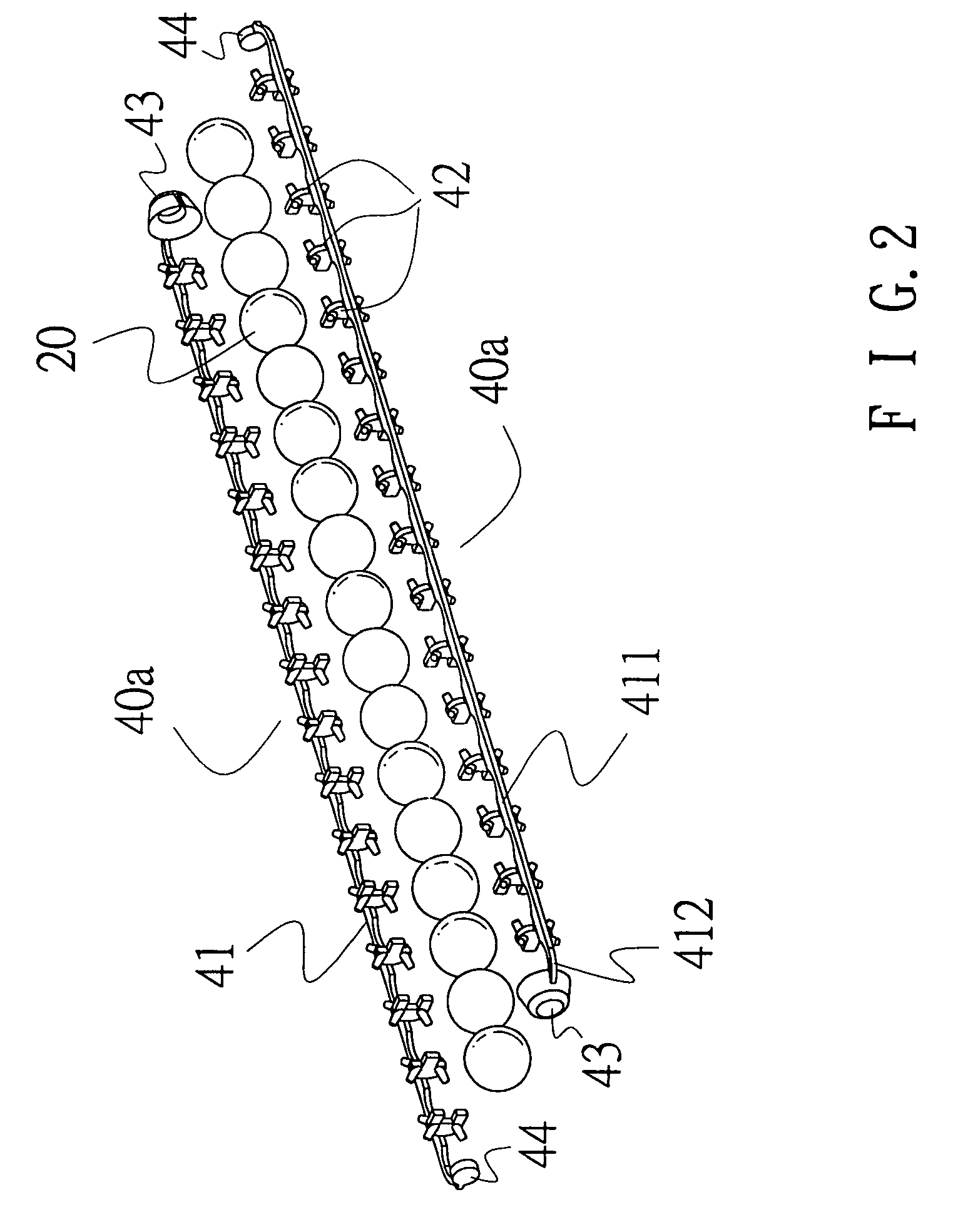
[0022]FIG. 2 is an exploded view of the clip-chain module of rolling unit of FIG. 1, it is learned from the drawing that the clip-chain module of rolling unit is made up of plural clip-chains, namely, a plurality of combinations of two half clip-chains 40a. Each of the half clip-chains 40a is made up of a link-belt 41, spacers 42 and end-parts 43, 44. The spacers 42 are connected together with the end-parts 43, 44 by virtue of receiving link-belt 411 together with end link-belt 412 of the link-belt 41. Wherein the spacers 42 serve to space out and receive the rolling elements 20, each paired neighboring spacers 42 define an interval for accommodation of a rolling element 20 and permitting it to roll therein.

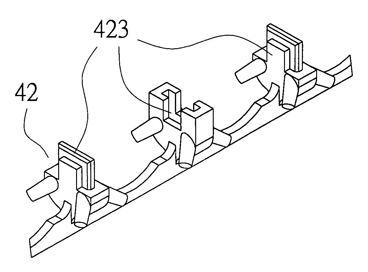
[0023]FIG. 3 is a partial amplified view of the half clip-chain of FIG. 2. It is learned from the drawing that each spacer 42 includes a base portion 421, a supporting portion 422 and an engaging portion 423. The engaging portions 423 of the spacers 42 are configured by manner of...

second embodiment

[0024]FIG. 4 is a partial amplified view of the half clip-chain of FIG. 2. Wherein on the engaging portion 423 of each spacer 42 is additionally provided with a fixing device, particularly on the top portion of engaging portion 423 is provided with a pin structure formed by manner of matching-pair. Furthermore, at both sides of the engaging portions 423 a rib structure is defined respectively by manner of matching-pair, such that prevent the disengagement of the spacers caused by angular torsion.

third embodiment

[0025]FIG. 5 is a partial amplified view of the half clip-chain of FIG. 2, wherein the additional fixing devices on the engaging portions 423 of the spacers 42 are configured in the shape of a spline and formed by like manner of matching-pair, such that prevents the disengagement of the spacers caused by angular torsion.

[0026]FIG. 6 is a cross sectional assembly view of the spacer of the clip-chain module of rolling unit in accordance with the present invention. Wherein each spacer 42 of the half clip-chain has an engaging portion 423 for serving to integrally combine two half spacers 42 together so as to form a complete spacer. The shape and dimension of the base portion 421 of each spacer 42 are decided by the configuration of the corresponding supporting portion 422 as well as the turning curvature of the rolling elements rolling in the slide block. As shown in FIG. 6A the combination of the spacer is strip-shaped, the engaging portions 423 are engaged together by an out-and-in m...


PUM


Abstract

The present invention relates to a clip-chain module of rolling unit, which structure had the spacers, the end-part and the link-belt. The characteristic of the clip-chain module of rolling unit was made up of one or upward half clip-chains, thereby can reduce the friction of the rolling element and improve the difficulty of the process. Therefore, this invention can enhance the competitiveness of this product.

Description

BACKGROUND OF THE INVENTION[0001]1. Field of the Invention[0002]The present invention relates to a clip-chain module of rolling unit, and more particularly to a receiving device for receiving rolling elements, which is applied to rolling units such as linear guide way, ball screw and linear rolling bearing. Normally the rolling unit is applied to mechanical, electronic, automatic equipment, semi-conduct device and the likes.[0003]2. Description of the Prior Arts[0004]The receiving device for receiving rolling elements of prior arts generally can be divided into two categories: first one is an independent individual receiver, and another one is a receiver made up of plural independent individuals. As shown in FIG. 11, wherein the slide block 11 is mounted onto a rail and slides thereon, which is interiorly provided with a plurality of rolling elements 20 and between every two neighboring rolling elements 20 is provided with a single receiver 30 so as to prevent the rolling elements 2...

Claims


Application Information

Patent Timeline
Patent Type & Authority Patents(United States)
IPC IPC(8): F16C29/06F16C33/46F16C33/50F16C33/38
CPCF16C29/0635F16C33/3825F16C33/506
Inventor WU, CHUN-LIANGWANG, CHIN-PEI
Owner HIWIN TECH
Why Eureka
Try Eureka