Replaceable leading edge for a marine drive unit

a technology of marine propulsion unit and leading edge, which is applied in the direction of marine propulsion, outboard propulsion units, vessel construction, etc., can solve the problems of affecting the performance of the marine propulsion uni

Inactive Publication Date: 2005-11-22
BRUNSWICK CORPORATION
View PDF19 Cites 22 Cited by
  • Summary
  • Abstract
  • Description
  • Claims
  • Application Information

AI Technical Summary

Benefits of technology

The patent describes a marine propulsion device with two different materials, one of which is made of aluminum and the other of which is made of a polymer material. The second portion is designed to be more crushable than the first portion and can include a crush box. The second portion can compress or absorb force without resiliently returning to its original shape. The technical effect of this design is improved impact absorption and reduced noise from the propulsion device.

Problems solved by technology

The technical problem addressed in this patent is how to protect the marine drive unit from damage caused by impact with objects like logs while still allowing easy installation and accurate positioning of any replaced parts. Additionally, the patent discusses different ways to introduce water into the drive unit for better cooling purposes.

Method used


Image

  • Replaceable leading edge for a marine drive unit
  • Replaceable leading edge for a marine drive unit
  • Replaceable leading edge for a marine drive unit

Examples


Embodiment Construction

[0039]Throughout the description of the preferred embodiment of the present invention, like components will be identified by like reference numerals.

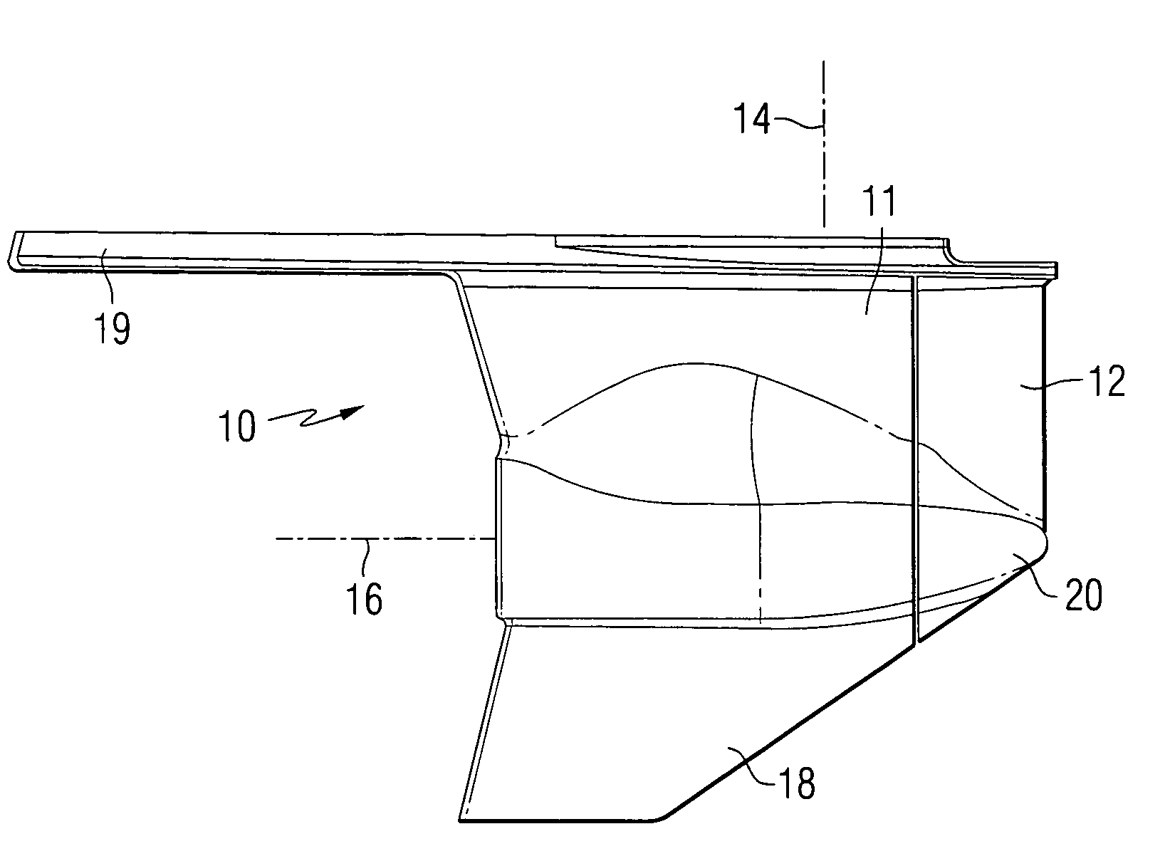
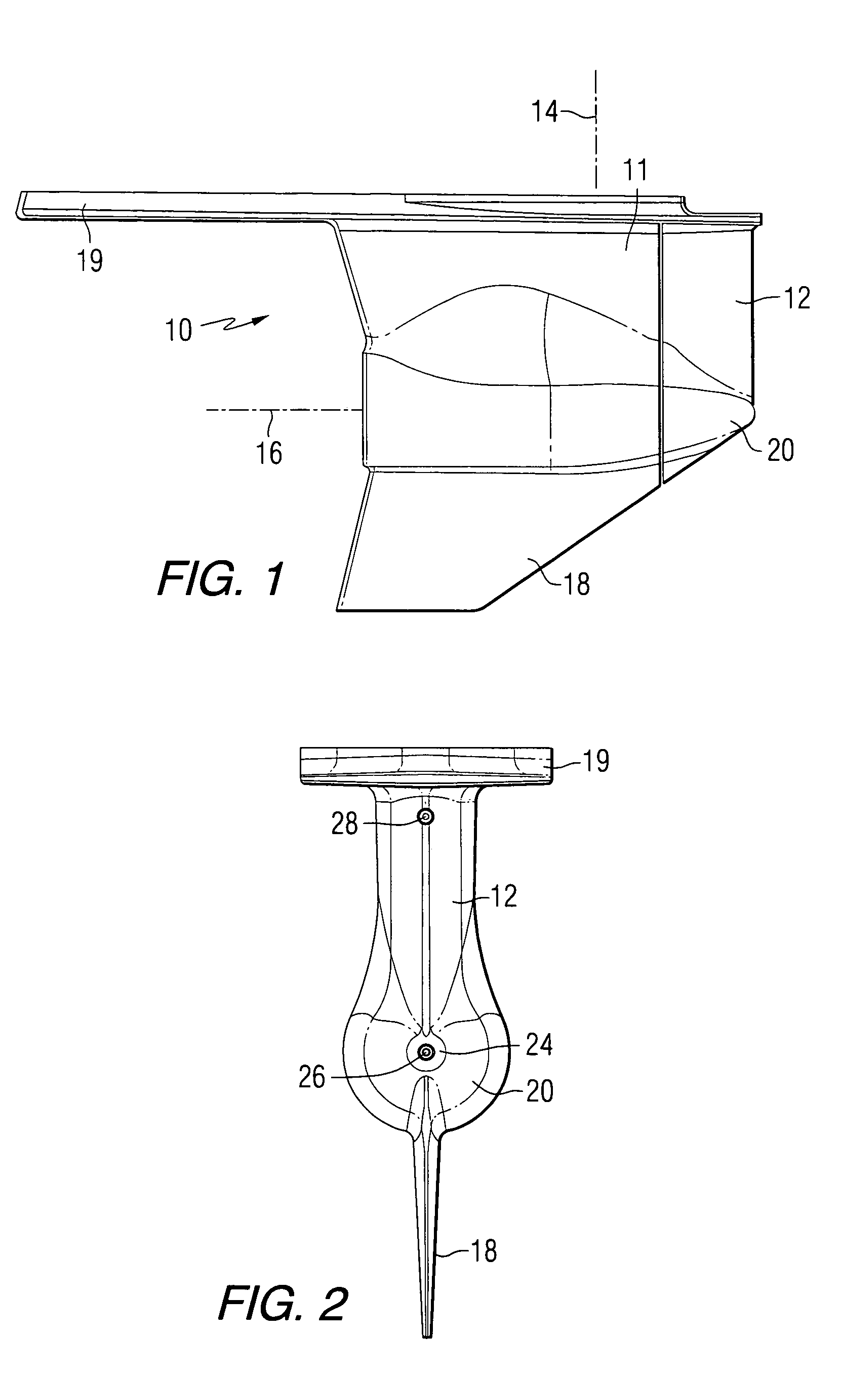
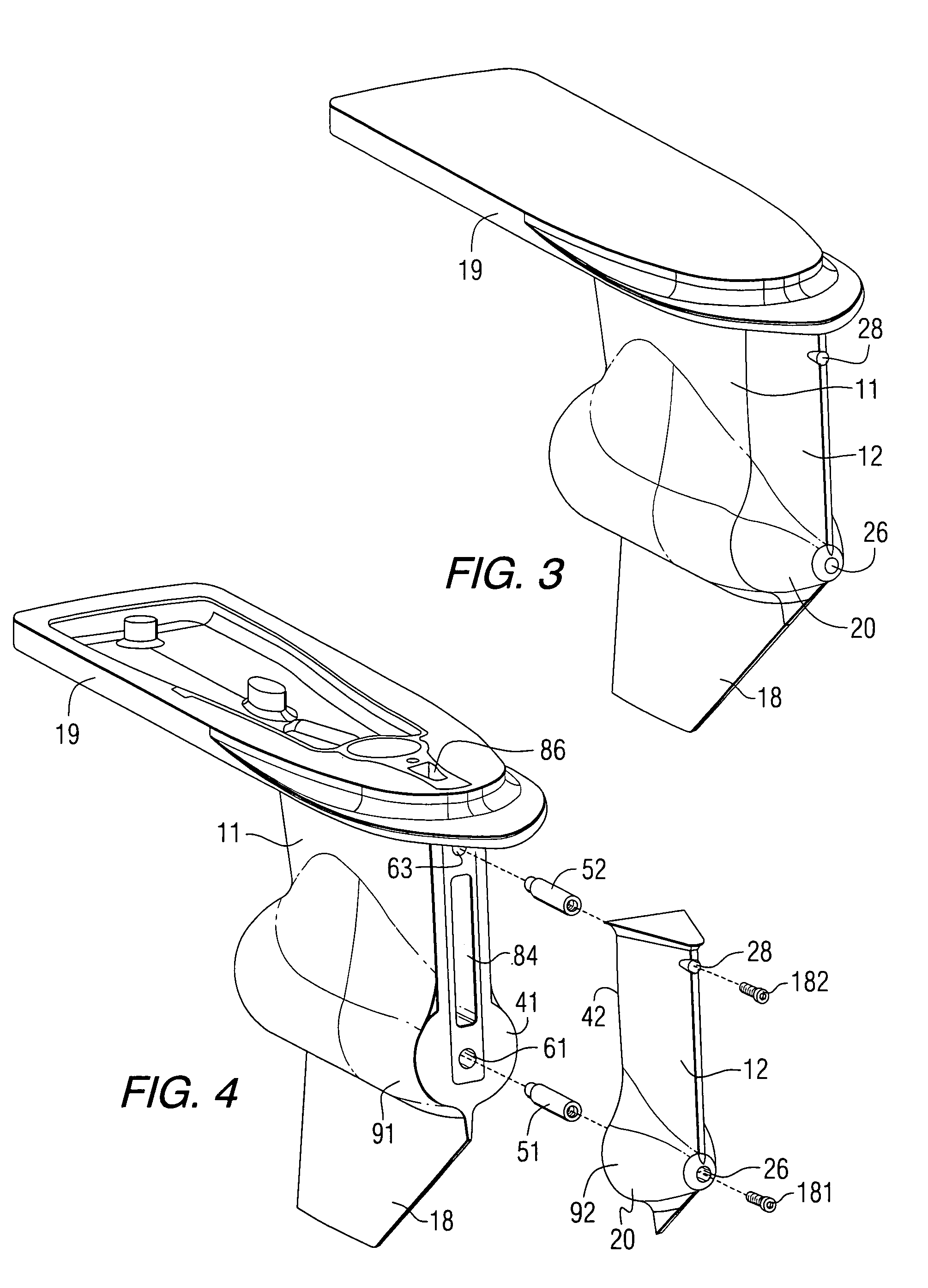
[0040]FIG. 1 is a side view of a gear case incorporating the present invention. Reference numeral 10 is used to designate the combined housing structure of the marine propulsion device that provides its gear case. A first portion 11 of the housing structure is intended to support and protect a drive shaft which rotates about a drive shaft axis 14 and a propeller shaft which rotates about a propeller shaft axis 16. Although the drive shaft and propeller shaft are not illustrated in FIG. 1, it should be understood that these components are well known to those skilled in the art and can be of a conventional design. A second portion 12 of the housing structure 10 is removably attachable to the first portion 11. Also shown in FIG. 1 is a skeg 18 and an anticavitation plate 19. The second portion 12 comprises a nose cone 20 that is shaped to ...


PUM


Abstract

A marine propulsion device is made of first and second portions which are removably attachable to each other. The second portion is the leading edge portion of the nose cone and the drive shaft housing. It can also comprise a portion of the skeg. The second portion is configured to crush more easily in response to an impact force than the first portion. This can be accomplished by making the second portion from a different material than the first portion, which can be aluminum, or by providing one or more crush boxes within the structure of the second portion to cause it to yield more quickly to an impact force and thus protect the first portion which is the more critical structure of the marine device.

Description


Claims


Application Information

Patent Timeline
Owner BRUNSWICK CORPORATION
Why Eureka
Try Eureka