

Direct clamp tooling for robotic applications
a technology of robotic applications and tooling, applied in the field of robotic finishing systems, can solve problems such as labor-intensive processes
- Summary
- Abstract
- Description
- Claims
- Application Information
AI Technical Summary
Benefits of technology
Problems solved by technology
Method used
Image

Examples
Embodiment Construction
[0025]The following description of the preferred embodiments is merely exemplary in nature and is in no way intended to limit the invention, its application, or uses.
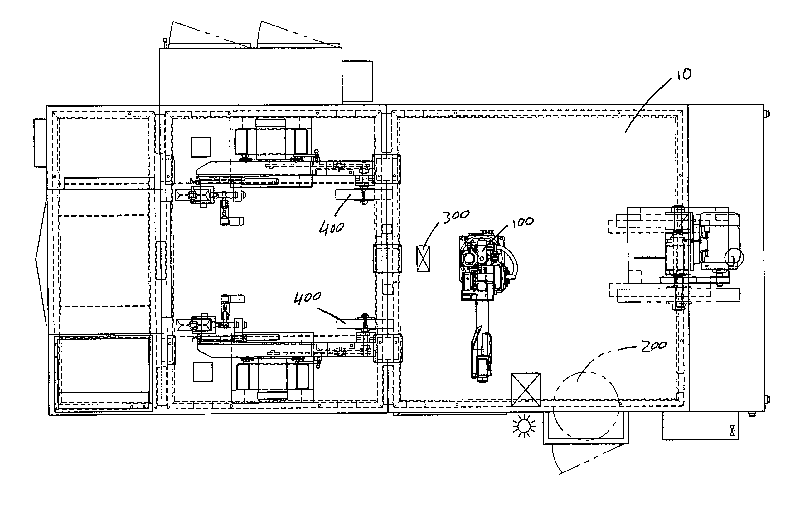
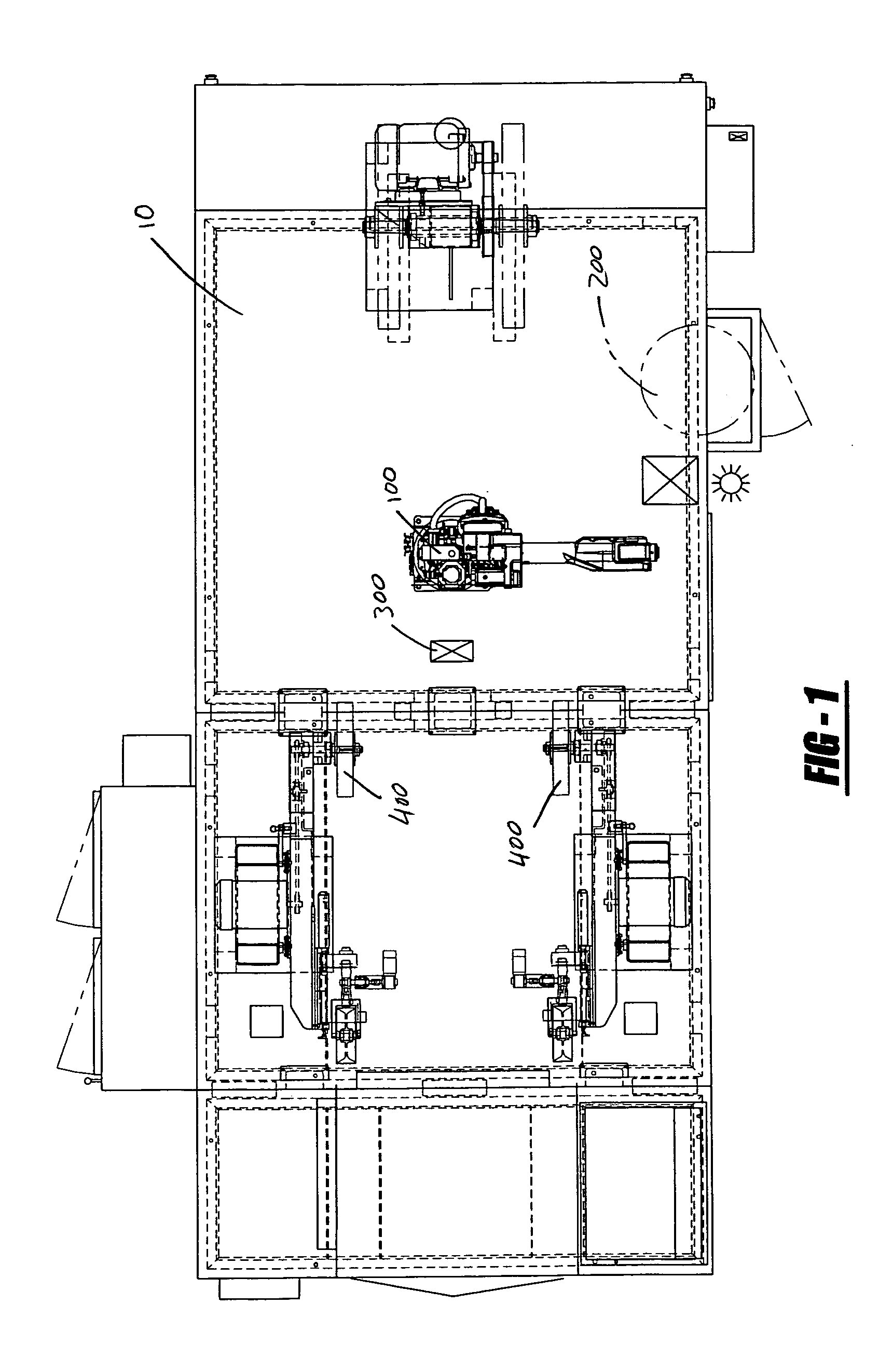
[0026]Referring to the drawings, FIG. 1 illustrates a robotic cell 10 used for robotically finishing metal articles such as knee implants. The cell 10 includes a robot 100, a revolving implant supply device 200, an implant reorientation station 300, and two finishing devices 400 in the form of stacked wheel heads. In operation, the robot 100 picks up a knee implant from the revolving part supply device 200 and manipulates the implant relative to the finishing devices 400 to perform buffing, polishing, and the like. To expose all surfaces of the implant to the finishing devices 400, the robot 100 sets the implant down on the implant reorientation station 300 and picks it back up from an opposite side. Finishing operations are thereafter continued.
[0027]Although other robots may be employed, it is presently preferred to e...
PUM
 Abstract
Description
Claims
Application Information