Helical broadhead

a broadhead and helical technology, applied in the field of archery broadheads, can solve the problems of arrow deflecting, arrow wobble and deflecting offline, and arrow placement accuracy, and achieve the effects of avoiding prolonged pain and suffering, avoiding excessive hemorrhaging, and efficient mortal wounds

Inactive Publication Date: 2005-11-22
HAJEK MICHAEL L
View PDF8 Cites 31 Cited by
  • Summary
  • Abstract
  • Description
  • Claims
  • Application Information

AI Technical Summary

Benefits of technology

[0010]A principle object and advantage of the present invention is that it provides for maximum penetration with a target drawing force to create excessive hemorrhaging caused by the spiraling elongate cutting blades causing a more efficient mortal wound.
[0011]Another object and advantage of the present invention is that it provides for a quick kill, successful retrieval, avoiding prolonged pain and suffering, and permits the avoidance of the long tracking process.
[0012]Another object and advantage of the present invention is that it provides accurate flight pattern caused by aggressive rotating of the broadhead due to the rifling design thereof.
[0013]Another object and advantage of the present invention is that the broadhead is self-penetrating and drawing inwardly which will avoid bone deflection and actually will draw the arrow through the target animal.
[0014]Another object and advantage of the present invention is that it provides for minimal friction with continuous cutting through the spiraling drawing energy action of the broadhead.
[0015]Another object and advantage of the present invention is that the broadhead spiraling or auger rotation effect reduces broadhead energy loss typical with known arrow shaft friction and torque.

Problems solved by technology

However, with faster and more powerful bows comes problems associated with the accuracy of arrow placement.
These known conventional broadhead blades seriously impede the rotation of the arrow and may in fact cause the arrow to wobble and deflect offline.
Bones cause the arrow to deflect and many times break the blade or divert the blade away from intended vital organs.
However, because the spiral blades have only the leading end locked down to the arrowhead, they appear to be fragile and may easily break upon impact with the target.
This is because they lack appropriate strengthening connections between the forward and rearward blade components and are completely mounted within a single slot within the ferrule.
The individual blades have a rearwardly located slight airfoil shape which may slightly assist in rotating the blade but offer little assistance in penetration.

Method used


Image

  • Helical broadhead
  • Helical broadhead
  • Helical broadhead

Examples


Embodiment Construction

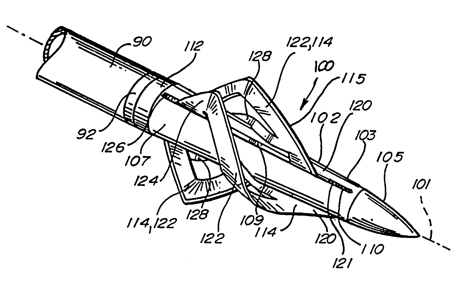
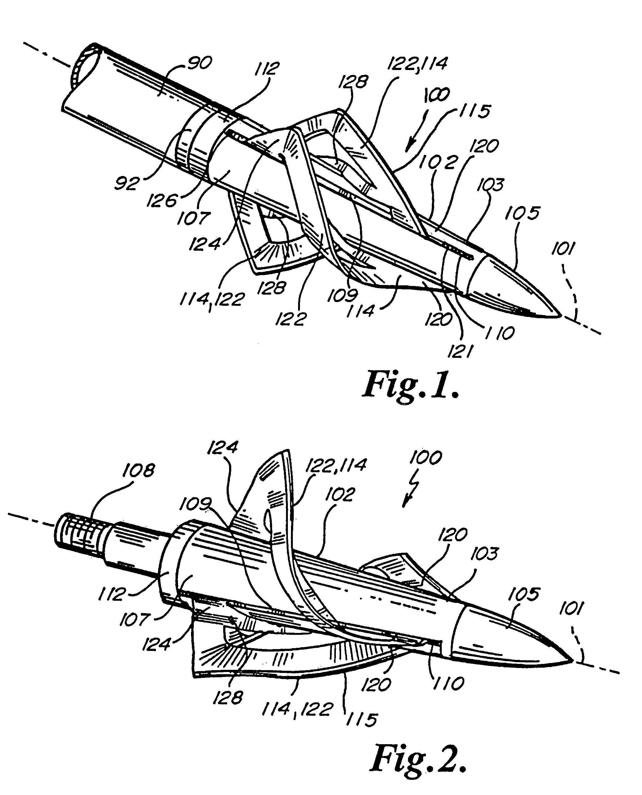
[0029]Referring to FIGS. 1 and 2, the broadhead 100 of the present invention generally may be appreciated mounted on arrow 90 by way of threaded insert 92. Broadhead 100 generally includes a tip 105 mounted on the ferrule 102 having blade mounting slots 109 in which is secured the blade assemblies 114 held in place by retention collar 112.

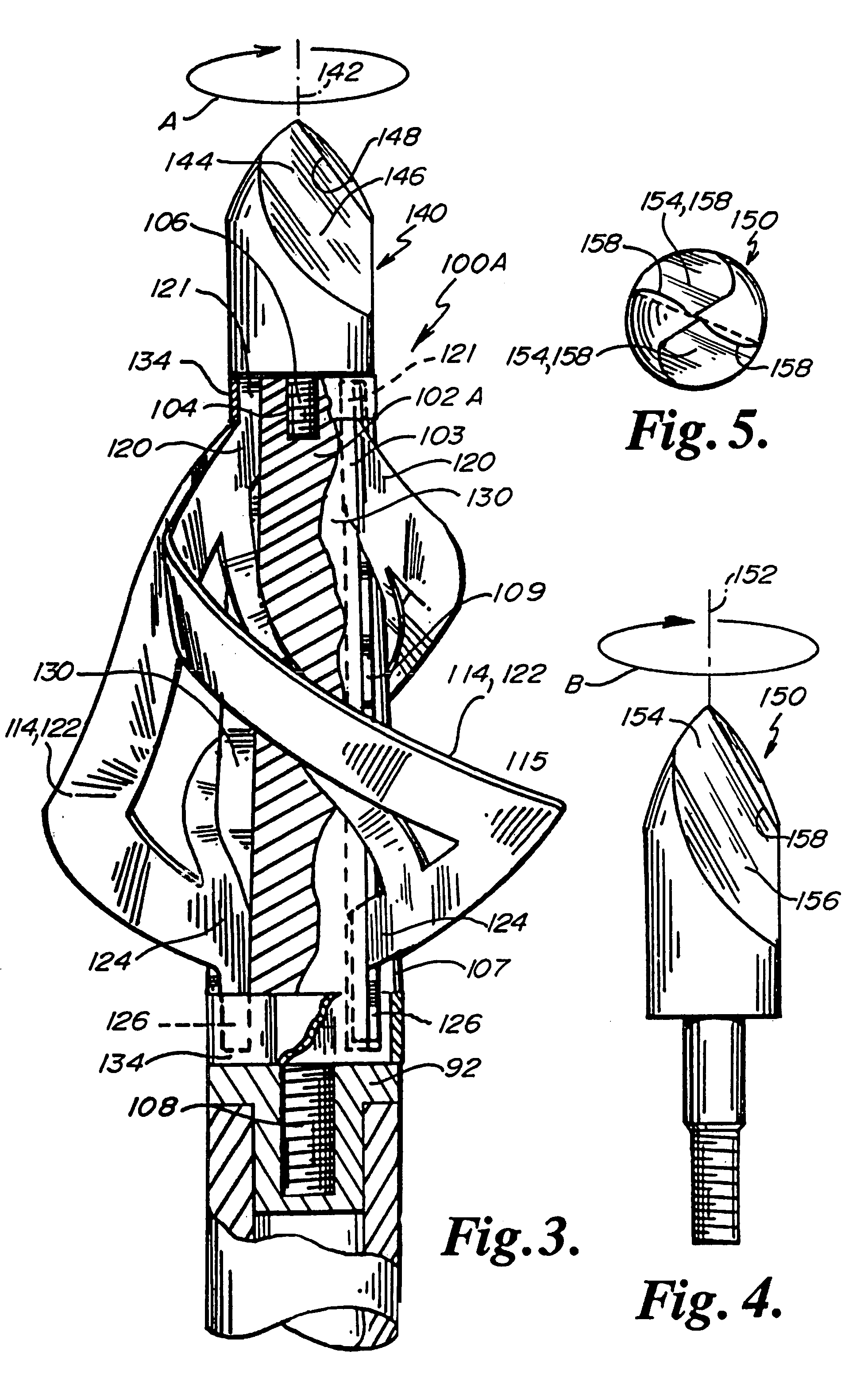
[0030]More specifically, broadhead 100 includes a longitudinal axis 101 running the length thereof. A body or ferrule 102 has a tip end 103 with a threaded longitudinal aperture 104 shown in FIG. 3. A broadhead trocar, point or tip 105 is secured into the threaded aperture 104 by way of the threaded shank boss or shaft 106 threaded into the longitudinal threaded aperture 104 at the tip end 103.

[0031]At the arrow end 107 of the ferrule 102 is located a threaded mounting stub 108. Blade mounting slots 109 are suitably located longitudinally and generally parallel with the axis 101 along the length of the ferrule 102. A slot pocket or forward slot por...


PUM


Abstract

A helical broadhead for an archery arrow includes a ferrule having a longitudinal axis with a tip end and an arrow end. Aligned forward and rearward slots are located in the ferrule generally parallel to the axis. At least two helical blade assemblies, each with an elongate cutting edge, spiral about the axis from a forward blade tang mounted in one forward slot to a rear tang mounted in a nonaligned, rearward slot. A chiseled tip having a sloping surface aligned with a helical blade assemblies may be attached to the tip end of the broadhead.

Description

BACKGROUND OF THE INVENTION[0001]The present invention relates to an archery broadhead, and more particularly, to a broadhead with helical blades having elongate cutting edges which impart spin to the arrow in flight to increase accuracy, penetration and hemorrhaging of the target animal.[0002]A bow hunter's goal at all times is accurately place a shot in a killing zone of a big game animal with maximum penetration to establish excessive hemorrhaging and ultimately result in a quick kill and successful animal retrieval thereby avoiding excessive tracking efforts, prolonged pain and suffering to be experience by the animal.[0003]To achieve the hunter's goal, the archery industry has provided faster shooting and more powerful bows with increased percentage of “let off” allowing the hunter to hold the drawn bow longer while aiming. However, with faster and more powerful bows comes problems associated with the accuracy of arrow placement. One aspect to assist in arrow accuracy and stabi...

Claims


Application Information

Patent Timeline
Patent Type & Authority Patents(United States)
IPC IPC(8): F42B6/00F42B6/08
CPCF42B6/08
Inventor HAJEK, MICHAEL L.
Owner HAJEK MICHAEL L
Why Eureka
Try Eureka