Deceleration platform

a technology of deceleration platform and water tank, which is applied in the direction of containers, non-canopied parachutes, containers to prevent mechanical damage, etc., can solve the problems of too deep penetration into the water, and the difficulty of reducing the impact force of the water, so as to reduce the potential damage to the payload and the effect of smooth load delivery

Active Publication Date: 2008-10-23
BABCOCK IP MANAGEMENT NUMBER ONE LTD
View PDF6 Cites 0 Cited by
  • Summary
  • Abstract
  • Description
  • Claims
  • Application Information

AI Technical Summary

Benefits of technology

[0006]Solutions to these problems have been sought. Particularly, by fashioning deployment platforms with a v-shaped cross-section, the force of impact with the water is spread more effectively, and potential damage to the payload is reduced. By the nature of the v-shape, these platforms also mean that in rough conditions the platform penetrates the water's surface to give a smooth load delivery.

Problems solved by technology

However, these v-profiled platforms also face problems.
If the angle of the v-profile is too acute, the platform may not be effectively decelerated on impact with the water, meaning that it may penetrate too deeply into the water and become submerged.
This can cause damage to the payload, and can adversely affect the stability of the deployment.
Also, the weight of the payload, if incorrectly mounted on the platform, may be sufficient to destabilise and even capsize the platform.
On the other hand, if the angle of the v-profile is too obtuse, the platform suffers a force on impact with the water great enough that the same force related problems occur as would with a flat-profiled platform.

Method used


Image

  • Deceleration platform
  • Deceleration platform
  • Deceleration platform

Examples


Embodiment Construction

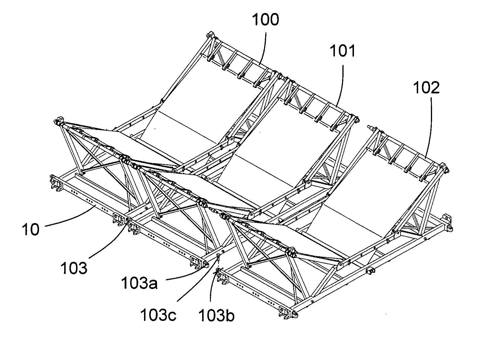
[0029]In an example embodiment of the present invention, the deceleration platform is formed from a flexible fabric material which is stretched over the cross members of a rigid frame to form a deceleration sheet.

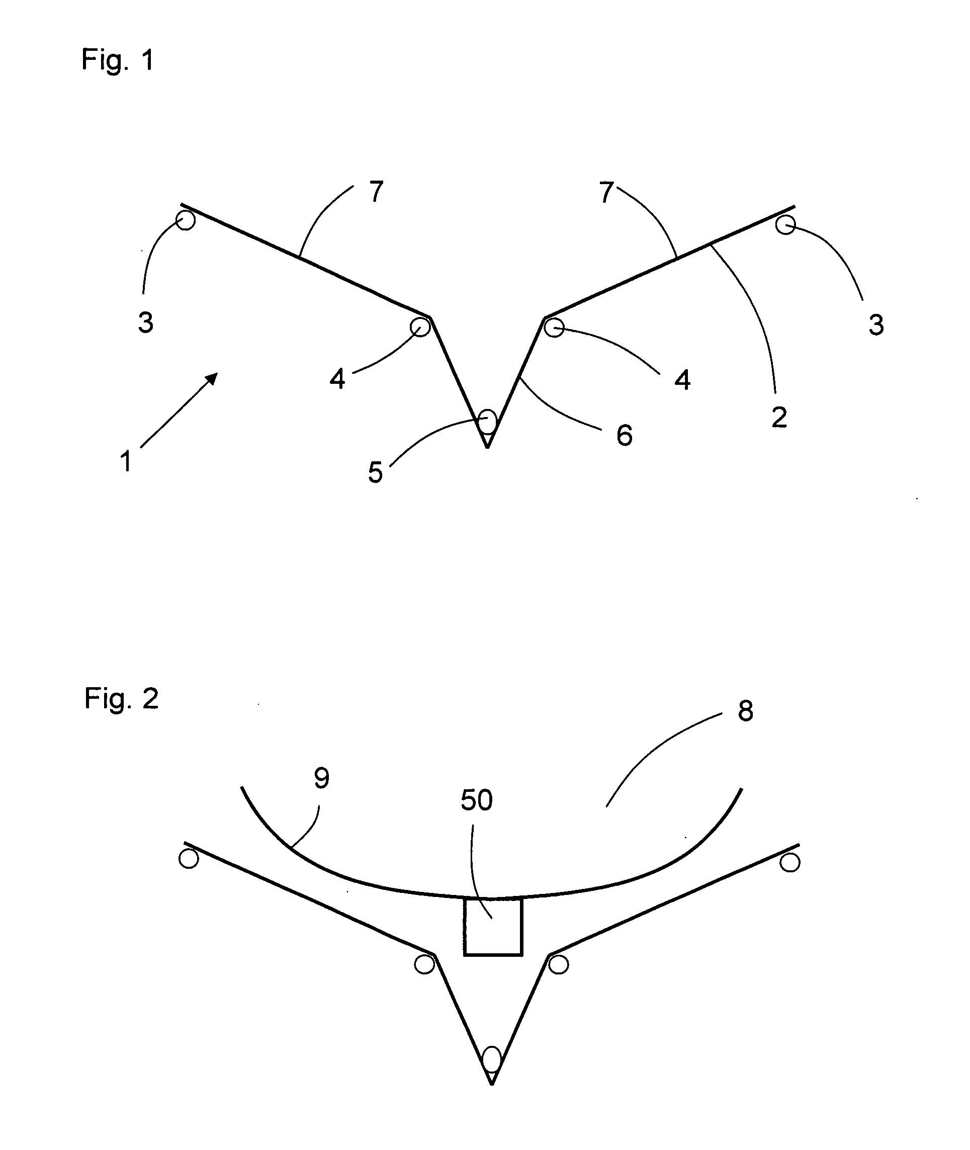
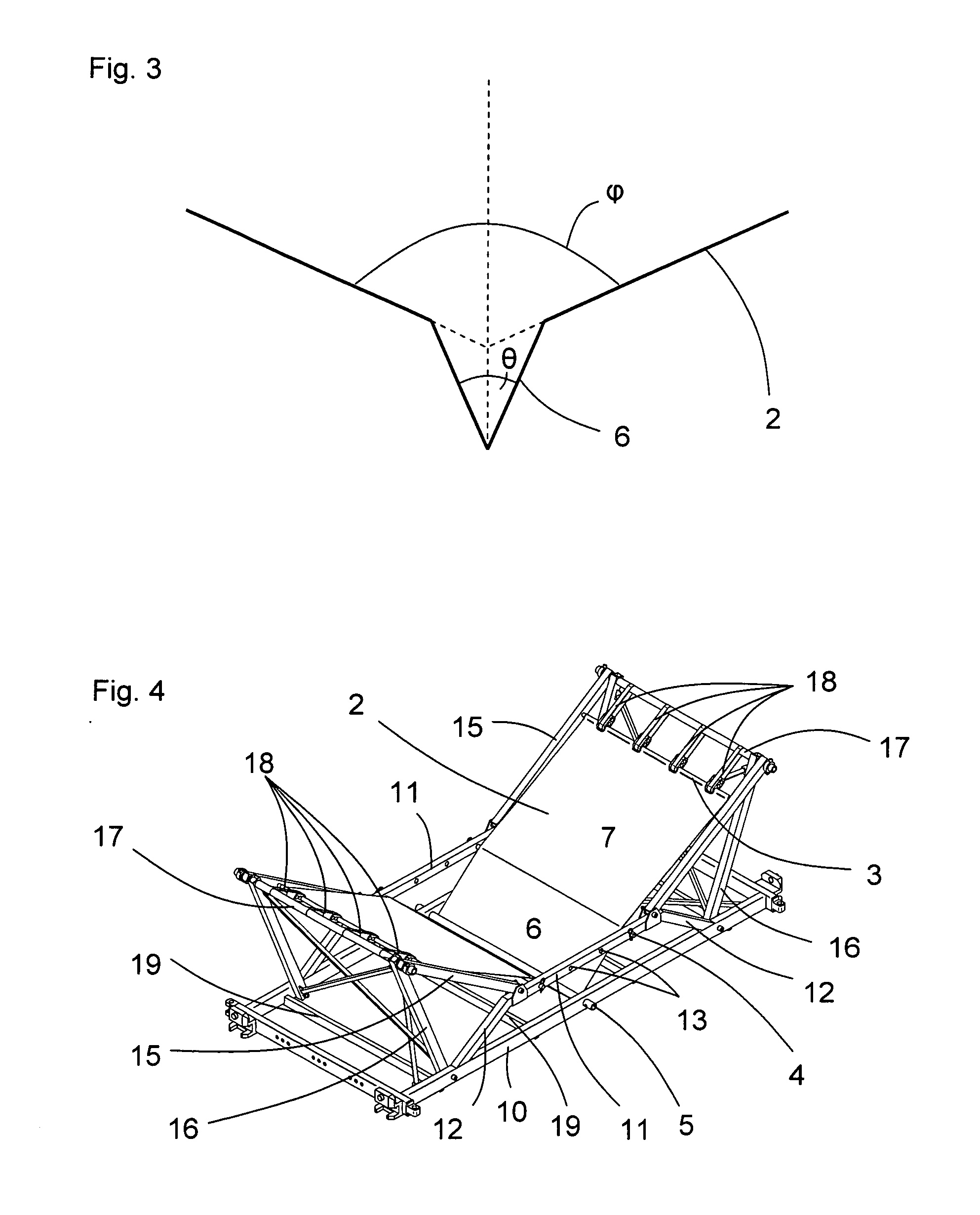
[0030]Deceleration sheet 1 shown in FIGS. 1 and 2 includes a flexible sheeting section 2 which is attached to a rigid frame (not shown). The flexible material can be of any suitable nature. Example materials include architectural textiles and rubber coated fabrics. The material of the rigid frame (not shown) is preferably rigid enough to provide a firm framework upon which the flexible sheet 1 can be mounted, and also light enough that the assembly is not of large weight. Such a large weight assembly would be uneconomical and potentially less effective in the present invention, as the increased mass of the frame will increase the force of impact of a platform dropped into a fluid.

[0031]The sheeting is tensioned by tubular elements 3 on each side of the frame. Any form of te...


PUM


Abstract

A platform for the aerial delivery of payloads into aquatic environments has a staged v cross-section formed by two walls extending from an end part. The portions of the two walls adjacent to the end part diverge from it at an angle θ and, together with the end part, form the tip of the platform. The remaining portions of the two walls, remote from the end part, form the body of the platform, and diverge at an angle φ that is greater than the angle θ. When the platform is deployed onto the surface of a fluid, it initially experiences a period of low deceleration as the tip penetrates the surface, followed by a period of higher deceleration, as the body contacts the surface.

Description

FIELD OF THE INVENTION[0001]1. Background of the Invention[0002]The present invention relates to platforms for the aerial delivery of payloads into aquatic environments, and more particularly to those which seek to protect the payload from the force of the impact of the platform with the water.[0003]2. Description of the Prior Art[0004]It is commonly desirable to deploy a payload or store directly into an aquatic environment from a carrier, for example an aircraft or larger surface vessel. This is conventionally achieved by strapping or otherwise mounting the payload onto a flat platform, which is then deployed from the carrier. Often an extractor parachute is used in this regard to slow the descent of the platform.[0005]A payload platform deployed in this way descends freely until impact with the water's surface. The water may well be extremely rough, and the payload itself may have been deployed from a substantial height. It is also likely that the payload is heavy. So, the force ...

Claims


Application Information

Patent Timeline
Patent Type & Authority Applications(United States)
IPC IPC(8): B64D1/14
CPCB64D1/14
Inventor SCHAFER, DAVID RICHARDBORLAND, GAVIN
Owner BABCOCK IP MANAGEMENT NUMBER ONE LTD
Why Eureka
Try Eureka