Electrical box mounting assembly

a technology for mounting assemblies and electrical devices, which is applied in the direction of electrical apparatus casings/cabinets/drawers, lighting conductor installation, and connection of devices, etc., can solve the problems of complex arrangement of supporting devices, unsatisfactory simplifying the remainder of the task, and difficult task for any installer, so as to simplify the task of mounting an electrical device to the ceiling. , the effect of greatly reducing the installation tim

Active Publication Date: 2005-11-22
ARLINGTON INDS
View PDF13 Cites 117 Cited by
  • Summary
  • Abstract
  • Description
  • Claims
  • Application Information

AI Technical Summary

Problems solved by technology

A second consideration arises from the awkwardness of working overhead.
Considering that the installer is typically on a ladder, this creates a challenging task for any installer.
This typically requires complex arrangements on the supporting device to accommodate a variety of boxes.
Although all of the above supporting devices include an arrangement for temporarily fastening the supporting device to overhead joists to free up an installer's hands, they are still not completely satisfactory for simplifying the remainder of the task for installing the electrical box and the light fixture or fan to the supporting device.

Method used


Image

  • Electrical box mounting assembly
  • Electrical box mounting assembly
  • Electrical box mounting assembly

Examples


Embodiment Construction

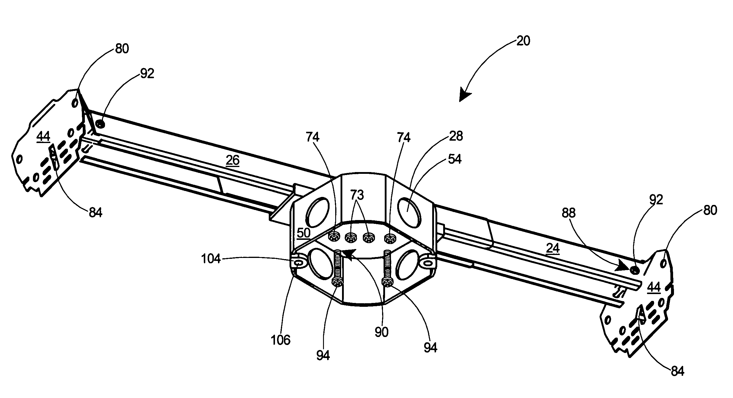
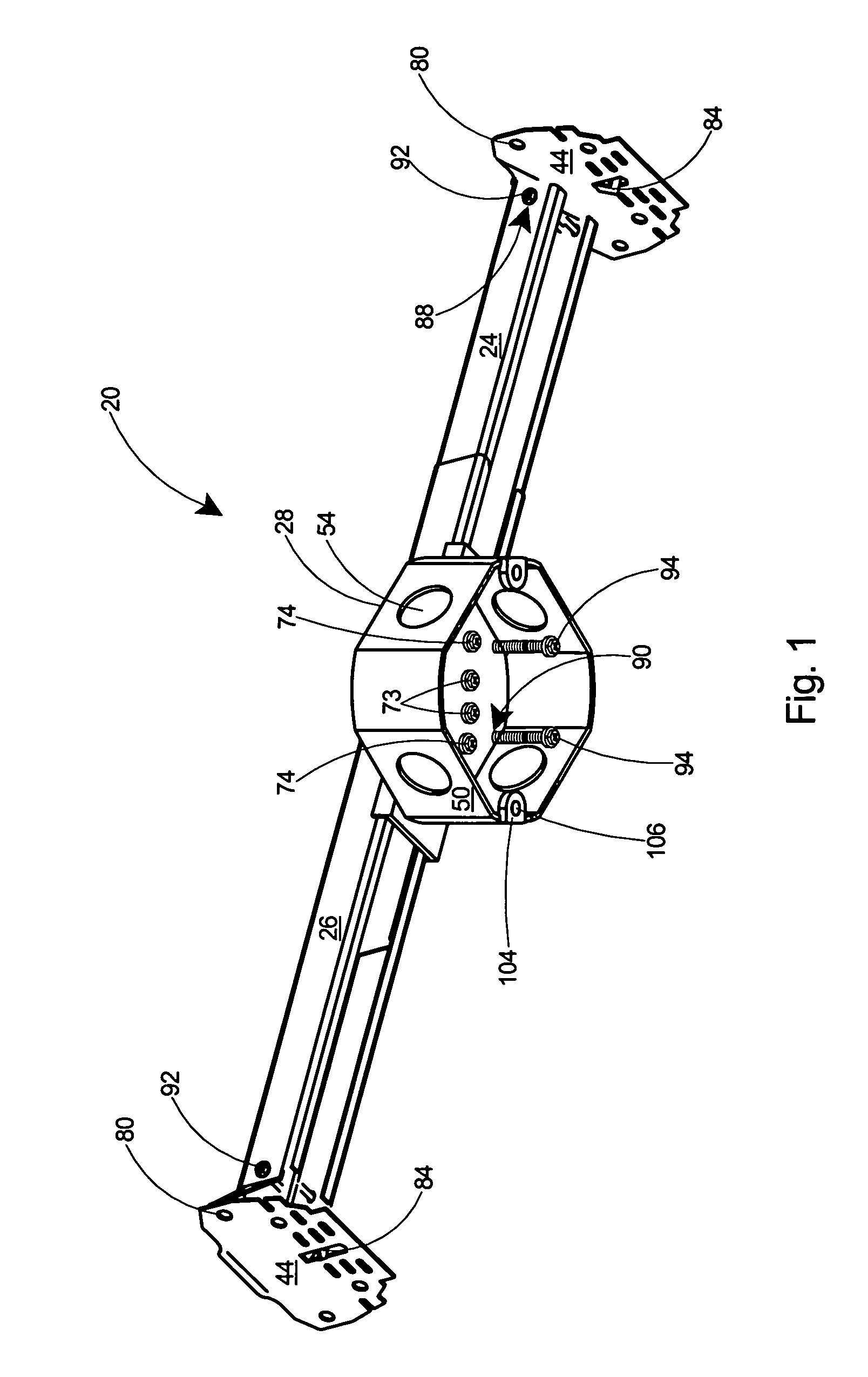
[0032]Referring to FIG. 1, there is depicted an electrical box mounting assembly 20 for securing an electrical device (not shown), such as a light fixture or a fan, to a ceiling. The electrical box mounting assembly 20 includes an adjustable mounting bar 22 including an inner 24 and an outer 26 tubular member, and an electrical box 28.

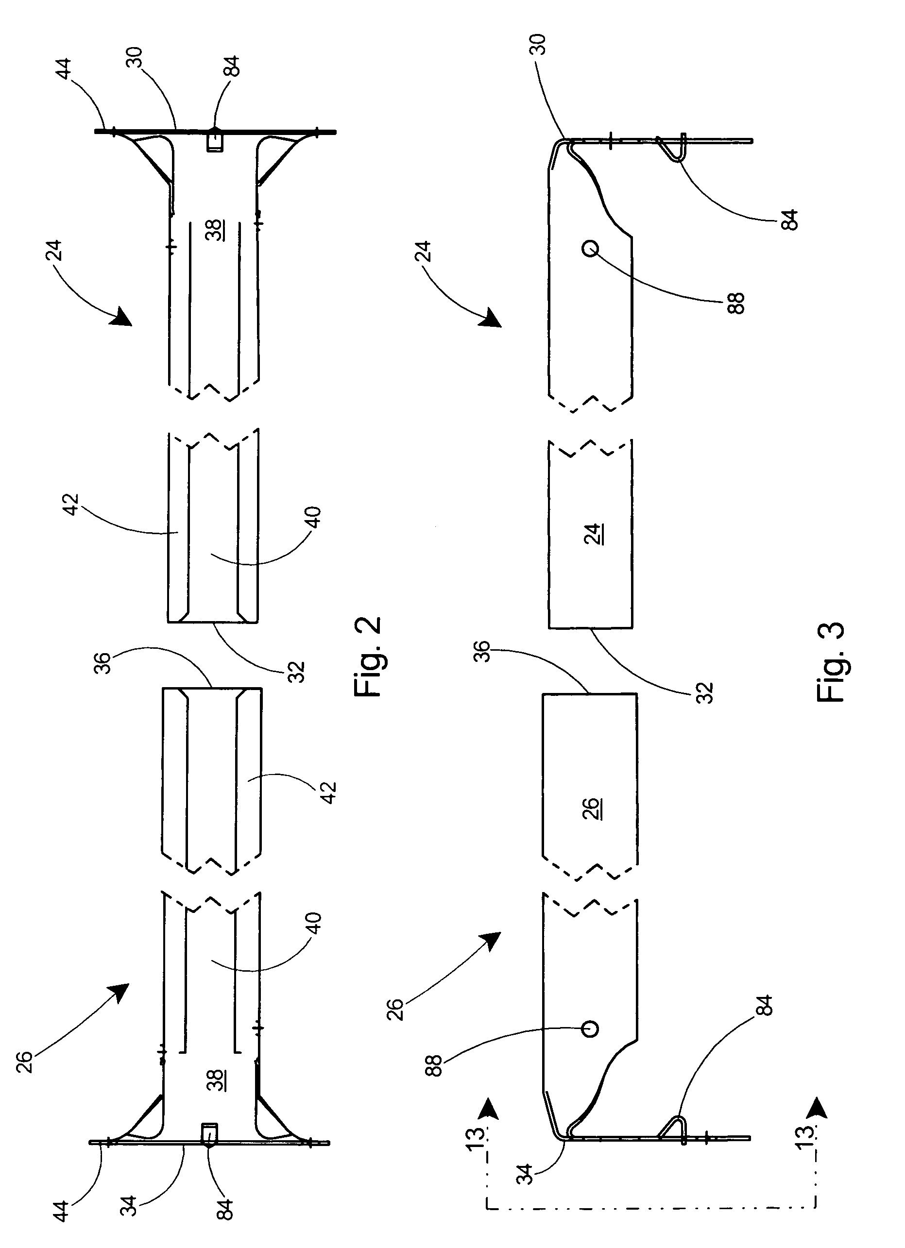
[0033]Referring to FIGS. 2–5, the inner tubular member 24 has an outer end 30 and an inner end 32. The outer tubular member 26 also has an outer end 34 and an inner end 36. Both of the tubular members 24, 26 have rectangular cross sections.

[0034]As shown in FIG. 5, the inner tubular member 24 has a smaller rectangular cross section than the outer tubular member 26, thereby enabling the inner tubular member 24 to be received in and slide with respect to the outer tubular member 26.

[0035]With reference to FIG. 2, the bottom sides 38 of each tubular member 24, 26 include longitudinal slots 40. Lips 42 surround the slots 40 and extend longitudinally along ...


PUM


Abstract

An adjustable mounting bar and electrical box assembly for hanging a light fixture, fan, or other electrical device from a ceiling. All hardware required for mounting the electrical device is included with the assembly. The adjustable mounting bar includes sliding tubular members with end flanges for spanning between adjacent overhead joists. An electrical box is connected to the tubular members by a clamp and outer clamping fasteners, which can be loosened to adjust the length of the adjustable mounting bar. The end flanges include penetrable tabs that can be driven into the overhead joists to temporarily secure the adjustable mounting bar to the joists and thereby free the installer's hands. The outer face of the end flanges include a series of rows of slots arranged horizontally thereon and forming a plurality of bend lines. To accommodate ceiling coverings of various thickness, the end flanges can be bent outwards at the proper bend line to position the lower end of the electrical box flush with the ceiling surface. Load bearing bar fasteners threadably engaged in temporary storage receptacles in the sliding tubular members are removed therefrom and fastened through the end flanges to securely fasten the mounting bar to the joists. Load bearing device fasteners threadably engaged in temporary storage receptacles in the electrical box are removed therefrom and driven into receptacles in the clamp to secure the electrical device to the mounting bar. Oversize openings are provided in the top wall of the electrical box to ensure that the entire suspended load is borne by the clamp and mounting bar and not the electrical box.

Description

FIELD OF THE INVENTION[0001]This invention relates to electrical junction boxes and specifically to an electrical box mounting assembly for mounting a fan or light fixture to a ceiling.BACKGROUND OF THE INVENTION[0002]Electrical boxes are commonly mounted on ceilings for the purpose of supporting ceiling fans, light fixtures, or other electrical devices. The electrical box provides a safe enclosure to house all wiring connections. Typically, these electrical boxes are secured to the ceiling by a supporting device that spans between two adjacent ceiling joists.[0003]Various considerations are necessary in providing supporting devices for ceiling-mounted electrical boxes. The National Electrical Code specifies a maximum weight of 80 pounds for ceiling light fixtures and a maximum weight of 70 pounds for ceiling fans. It is therefore very important that an installer use adequate load-bearing fasteners for securing the supporting device to the overhead joists. It is also important that ...

Claims


Application Information

Patent Timeline
Patent Type & Authority Patents(United States)
IPC IPC(8): H01H13/04H01H9/02H02G3/12
CPCH02G3/125Y10S248/906
Inventor GRETZ, THOMAS J.
Owner ARLINGTON INDS
Why Eureka
Try Eureka