Concealed fastener, system, and associated methods

a technology of fasteners and concealed parts, applied in the direction of wrenches, screwdrivers, constructions, etc., can solve the problems of unsightly fastener heads, future problems, crack propagation, fungal and mold growth, etc., and achieve the effect of adequate spacing

Active Publication Date: 2006-05-16
KREG ENTERPRISES
View PDF25 Cites 55 Cited by
  • Summary
  • Abstract
  • Description
  • Claims
  • Application Information

AI Technical Summary

Benefits of technology

[0007]The present invention achieves the following objectives: Adequate spacing between surface members is provided for aeration; surface members are attached directly to supporting joists; individual surface members are removable after installation; variable-dimension construction materials are usable, including, but not intended to be limited to, hardwood, softwood, polymeric, and composite materials; butt joints, endings, and perpendicular and diagonally oriented surface members are fastenable; surface members are not required to be completely fastened sequentially; shrinkage of surface members does not compromise the integrity of the completed construction.

Problems solved by technology

This method has several shortcomings: the visible fastener heads are unsightly and detract from the appearance of the deck surface, and the surface penetration with the fasteners can lead to future problems.
Such problems include those resulting from moisture penetration, causing material changes resulting in splintering, crack propagation, fungal and mold growth, and loosening of the junction between the fastener and the surrounding material.
These problems can cause the decking to become loose and stained by material corrosion.
In addition, the decking members can become loose, and the fastener head can protrude above the deck surface, all of which are potentially dangerous to deck users.

Method used


Image

  • Concealed fastener, system, and associated methods
  • Concealed fastener, system, and associated methods
  • Concealed fastener, system, and associated methods

Examples


first embodiment

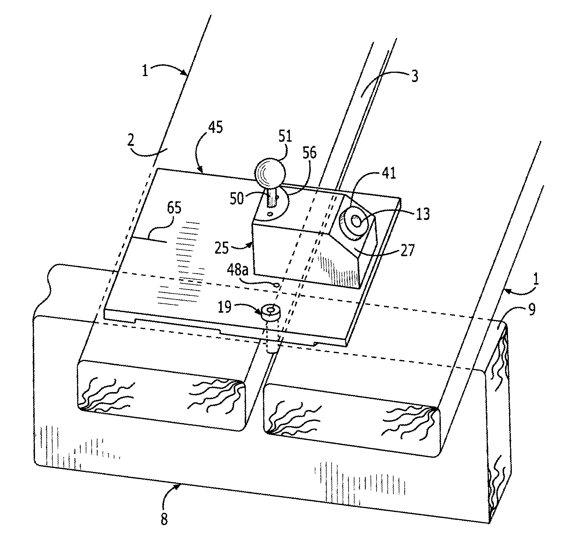
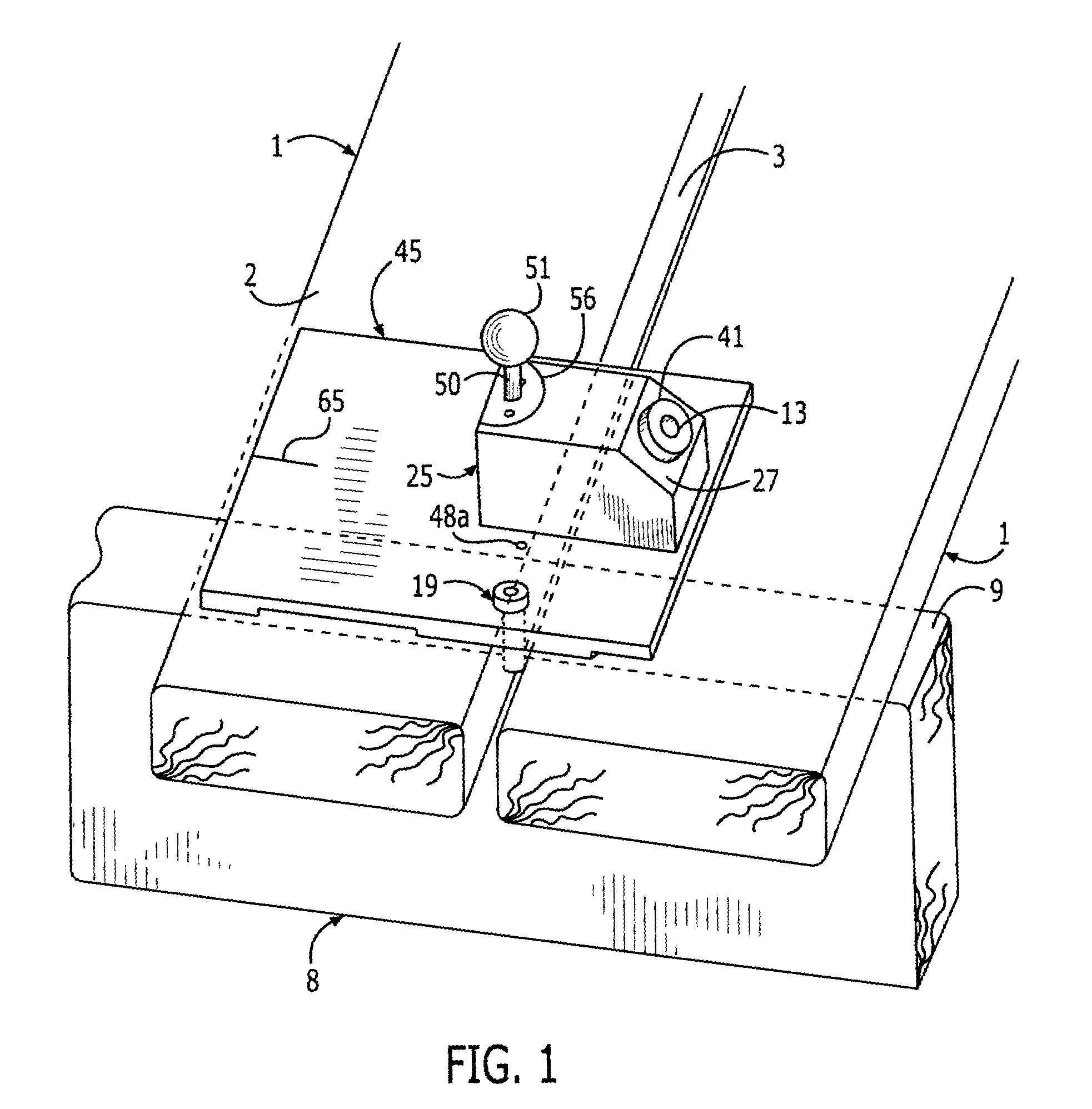
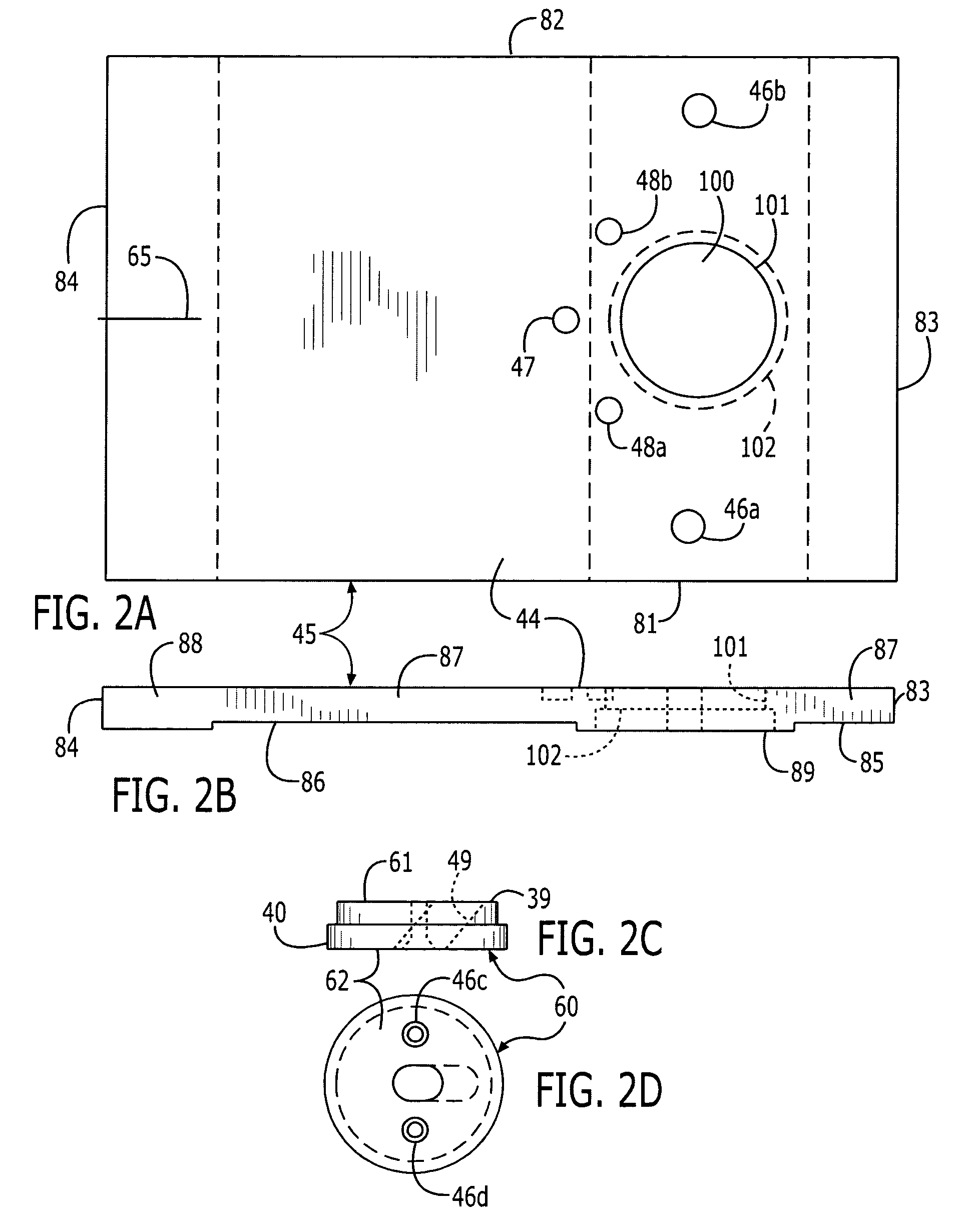
[0050]a method of use is intended for decking member materials that require predrilling of a pilot hole 71. Predrilling minimizes the chance of splitting the decking member 1, or breaking or stripping the head 74 of the fastener 70, especially when using hardwoods. Pressure is applied to the top surface 44 of the base plate 45, such as by the user's knee or foot. A centering drill bit 35 (FIG. 7) is attached to a power drill at a top end 91, introduced into the top end 13 of the guide sleeve 12, and advanced until its distal tip 37 enters the side face 3 of a decking member 1, creating a pilot hole 71 with a chamfered lead-in 72 (FIG. 5B). A desired depth is adjusted by a correct positioning of an adjustable stop collar 36 on the drill bit 35 (FIG. 7). The upper, nonfluted, portion 40, having a larger diameter, matches the internal diameter of the guide sleeve 12, thus keeping the tip 37 of the smaller-diameter, fluted portion 39 properly aligned along the central axis 28 as the dri...

second embodiment

[0054]a method of use is intended for decking member materials that do not require predrilling of a pilot hole. Pressure is applied to the top surface 44 of the base plate 45, such as by the user's knee or foot. A fastener 70 is loaded into the top opening 13 of the guide sleeve 12, followed by the driver 31 attached to a power drill. The driver 31 advances the fastener 70 until it is properly seated, as determined by the stop collar 34 on the driver 31.

[0055]As alluded to above, the appropriate angle 15 is an important feature of the present invention, since it represents an appropriate orientation such that the fastener 70 has adequate access to the side face 3 of the decking member 1 through the space 59 between decking members 1. As mentioned, an angle 15 above the desired range can subject the fastener 70 to walking downward and to inadequate purchase; an angle 15 less than the desired range creates less access to the side face 3, because the central axis 28 becomes more tangen...


PUM


Abstract

A device for affixing a decking member to a joist includes a jig body positionable atop a pair of spaced-apart decking members positioned atop a joist. The jig body has an angled bore having a bottom end extending through a bottom face of the jig body, the bottom end of the angled bore in communication with the space between the decking members. The angled bore defines a centerline extending through the space to a position on the side of the first structural member. The angled bore is for receiving a fastener drivable therethrough into the first structural member's side face, through the first structural member's bottom face, and into the second structural member's top face.

Description

CROSS-REFERENCE TO RELATED APPLICATION[0001]This application claims priority from commonly owned provisional application Ser. No. 60 / 372,735, filed Apr. 16, 2002, “Universal Hidden Fastening System for Decks.”BACKGROUND OF THE INVENTION[0002]1. Field of the Invention[0003]The present invention relates to construction systems and methods, and, more particularly, to fasteners for outdoor structures such as decks.[0004]2. Description of Related Art[0005]Conventional deck fastening methods incorporate the placement of fastening means, such as screws, nails, or staples, directly into the surface of the decking material, through the decking members, and into a support joist positioned beneath the decking members. This method has several shortcomings: the visible fastener heads are unsightly and detract from the appearance of the deck surface, and the surface penetration with the fasteners can lead to future problems. Such problems include those resulting from moisture penetration, causing...

Claims


Application Information

Patent Timeline
Patent Type & Authority Patents(United States)
IPC IPC(8): B25B1/20B25B23/00
CPCB25B23/00E04F15/02183E04F21/22
Inventor BOLTON, CARL WILLIAM
Owner KREG ENTERPRISES
Why Eureka
Try Eureka