Probe card and contactor of the same

a technology of contactor and probe card, which is applied in the field of probe card, can solve the problems of ineffective economic efficiency, ineffective time and economic efficiency, and inability to meet the needs of the user, and achieve the effect of excellent contact stability

Inactive Publication Date: 2005-11-22
NIHON DENSHIZAIRYO
View PDF9 Cites 34 Cited by
  • Summary
  • Abstract
  • Description
  • Claims
  • Application Information

AI Technical Summary

Benefits of technology

[0009]The present invention is made to solve the above problems in the conventional probe card. It is an object of the present invention to provide a probe card in which excellent contact stability with an object to be tested is provided and only a contactor which is deformed or damaged because of repetitive contacts can be easily exchanged.
[0010]In addition, it is another object of the present invention to provide a contactor which is excellent in contact stability with an object to be measured and easily exchanged when deformation or a damage is generated because of repetitive contacts.

Problems solved by technology

The lateral type probe card has an aspect which is not suitable for measuring many chips at the same time, which is required under the circumstances in which large-scale integration of the LSI chip is implemented and a tester is multiplexed, hence its use is decreasing.
However, as shown in FIG. 8, according to the conventional probe card, since the contactor 6 is fixed by soldering directly to the contactor mounting substrate (space transformer 2), when deformation or a damage of the contactor 6 because of repetitive contacts is generated, it is necessary to exchange the contactor mounting substrate (space transformer 2) itself, which is very ineffective in terms of time and economical efficiency.
Although there is an improvement as compared with an example shown in FIG. 8, the economical efficiency is still ineffective.

Method used


Image

  • Probe card and contactor of the same
  • Probe card and contactor of the same
  • Probe card and contactor of the same

Examples


embodiment 1

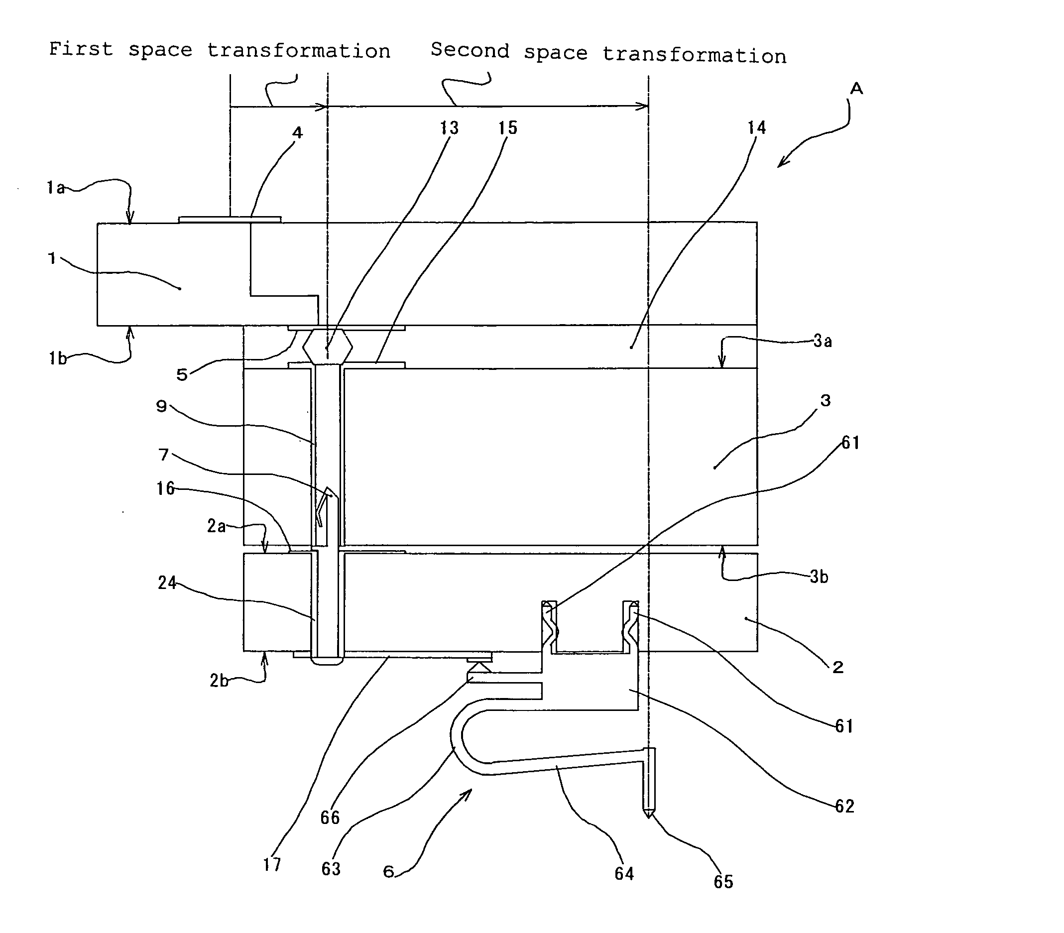
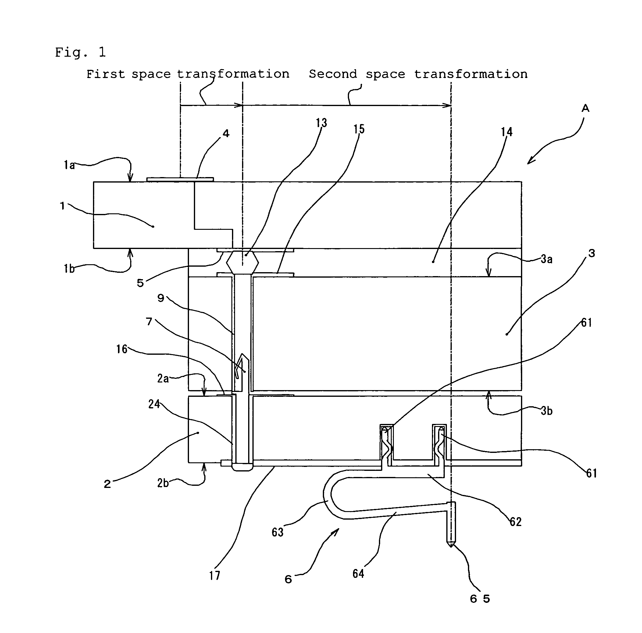
[0052]FIG. 1 is a sectional view showing a part of a probe card A provided with a detachable contactor 6 of the present invention, FIG. 2 is an enlarged view showing the detachable contactor 6 of the present invention, FIG. 3a to 3d are views showing a variation of shapes of insertion parts 61, FIG. 4a to 4d are views showing another variation of the shapes of the insertion parts 61, FIG. 5 is an enlarged view showing another detachable contactor 6 of the present invention, FIG. 6 is an enlarged view showing still another detachable contactor 6 of the present invention, FIG. 7 is an enlarged view showing still another detachable contactor 6 of the present invention, FIG. 8 is an exploded schematic view showing a sectional structure of a probe card having a conventional connecting pattern of a contactor, and FIG. 9 is an exploded schematic view showing another sectional structure of a probe card having a conventional connecting pattern of a contactor.

[0053]FIG. 1 is a sectional view ...

embodiment 2

[0077]FIG. 10 is a sectional view showing a part of a probe card A provided with a detachable contactor 6 of the present invention, FIG. 11 is an enlarged view showing the detachable contactor 6 of the present invention, FIGS. 12a to 12d are views showing a variation of configurations of insertion parts 61, FIGS. 13a to 13d are views showing another variation of the configurations of the insertion parts 61, FIG. 14 is an enlarged view showing another detachable contactor 6 of this embodiment of the present invention, FIG. 15 is an enlarged view showing still another detachable contactor 6 of this embodiment of the present invention, FIG. 16 is an enlarged view showing still another detachable contactor 6 of this embodiment of the present invention, FIG. 17 shows an example in which an electrode part 66 in an example shown in FIG. 10 protrudes in the opposite direction from the arm part 64 (including the curve part 63), FIG. 18 shows an example in which the electrode part 66 in an ex...


PUM


Abstract

A probe card used for measuring electrical characteristics of a semiconductor device such as an LSI chip and comprising a contactor mounting substrate on which a plurality of contactors are arranged, in which the contactor comprises an insertion part for mounting the contactor on the contactor mounting substrate, a support part for supporting the insertion part and performing positioning in the height direction by contacting a surface of the contactor mounting substrate, an arm part extending from the support part, and a contact part arranged at a tip end of the arm part to come in contact with an electrode of an object to be tested, and the insertion part is detachably mounted on an electrode hole provided in the surface of the contactor mounting substrate and made to be conductive by a wiring pattern.

Description

BACKGROUND OF THE INVENTION[0001]1. Field of the Invention[0002]The present invention relates to a probe card which measures electrical characteristics of a semiconductor device such as an LSI chip and it relates to a mounting structure of a contactor which comes in contact with the semiconductor device.[0003]2. Description of the Background Art[0004]There are a lateral type called cantilever type and a vertical type called perpendicular type in a probe card which measures electrical characteristics of a semiconductor device such as an LSI chip. The lateral type probe card has an aspect which is not suitable for measuring many chips at the same time, which is required under the circumstances in which large-scale integration of the LSI chip is implemented and a tester is multiplexed, hence its use is decreasing. Meanwhile, since the vertical type probe card can use many probes and provides a high degree of freedom for a probe arrangement and it is suitable for measuring many chips at...

Claims


Application Information

Patent Timeline
Patent Type & Authority Patents(United States)
IPC IPC(8): G01R1/067G01R1/073H01L21/66
CPCG01R1/06733G01R1/06727G01R1/07314H01L22/00
Inventor MORI, CHIKAOMISATOU, KATSUHIKO
Owner NIHON DENSHIZAIRYO
Why Eureka
Try Eureka