
Fluid barrier arm cuff

Inactive Publication Date: 2005-11-29
JOZ
View PDF26 Cites 8 Cited by
  • Summary
  • Abstract
  • Description
  • Claims
  • Application Information

AI Technical Summary

Benefits of technology

[0008]The present invention has numerous advantages. For instance, the present invention can be worn over the skin or over any garment to seal the space between the apparatus and the arm or clothing. The apparatus provides a suitable barrier against fluids traveling down the arm or clothing. The apparatus is not required to be attached to a glove or a mitt or any other garment. In this respect, the apparatus of the invention is an independent unit. The use of less material makes the invention a more economically attractive option than mitts or gloves. The present invention includes a drain at a specific location which can be directed to drain the fluids in any direction, which is particularly advantageous to avoid being drenched.

Problems solved by technology

Inevitably, the water from the hose runs down the individual's arm to other parts of the body, and drenches their clothing.
This is an uncomfortable situation, often made more uncomfortable if the water is cold.
This is considered unsafe because in the event the horse becomes startled, it may move sideways into the stepstool or ladder and become entangled and injure itself or the individual washing the horse.

Method used


Image

  • Fluid barrier arm cuff
  • Fluid barrier arm cuff
  • Fluid barrier arm cuff

Examples


Embodiment Construction

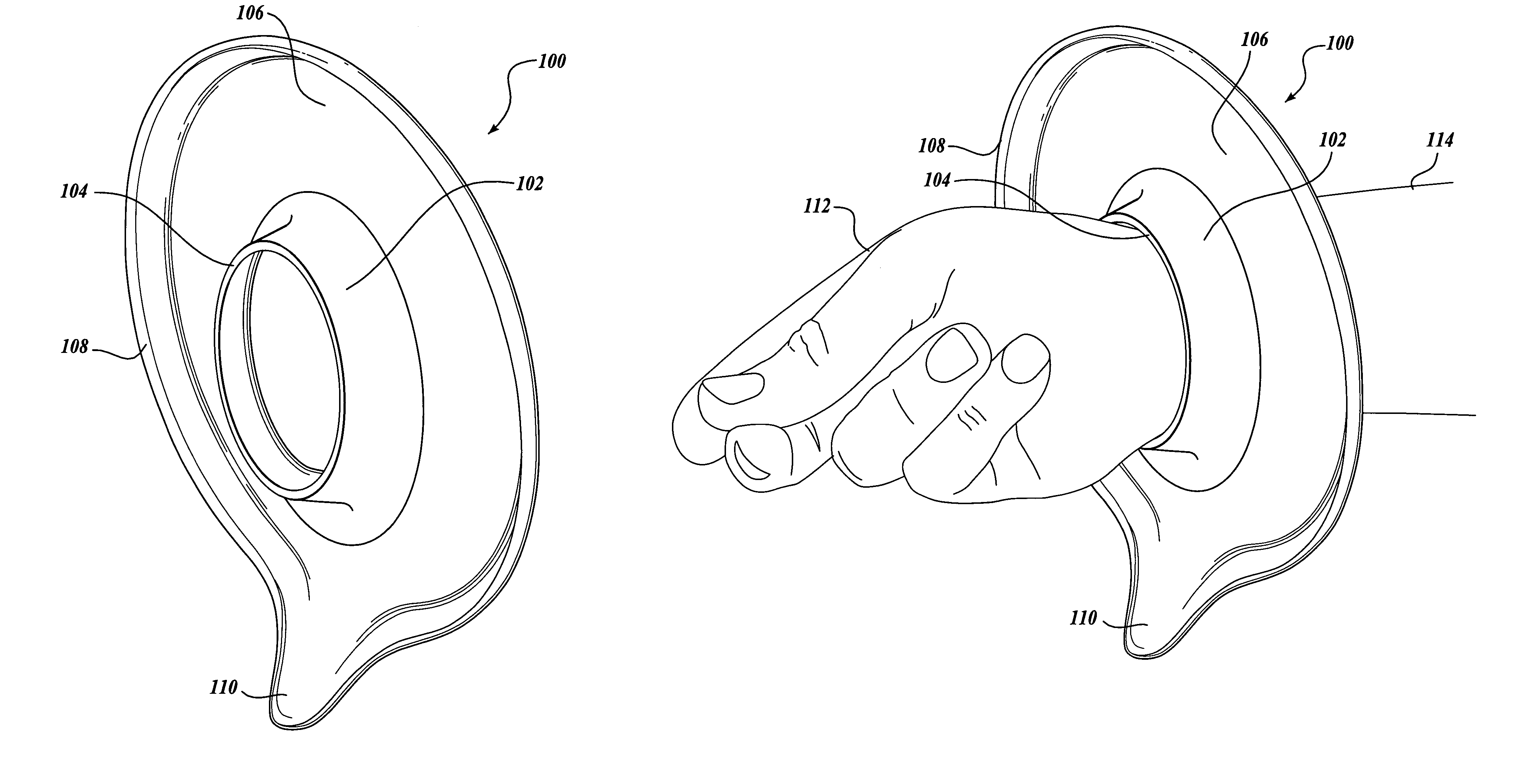
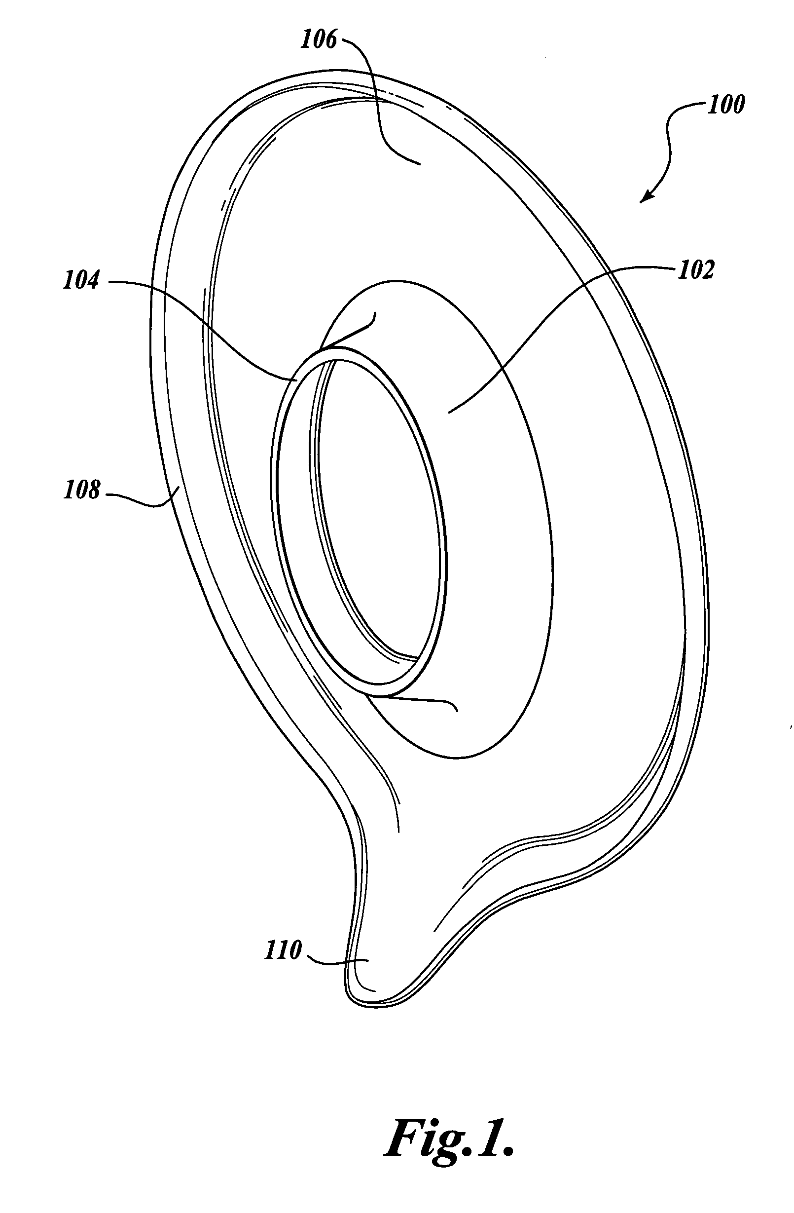
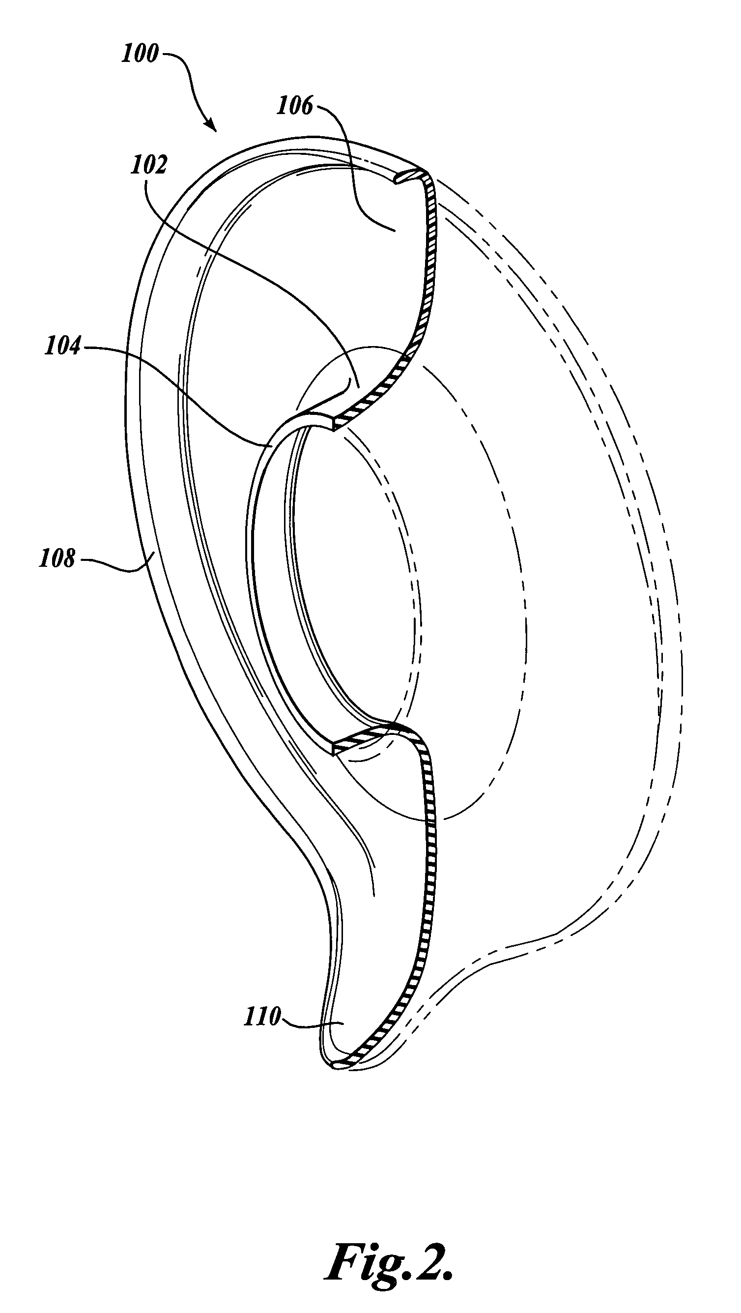
[0016]Referring collectively to FIGS. 1 and 2, one embodiment of a fluid barrier apparatus 100 for a wrist or any other part of the arm is illustrated. The fluid barrier apparatus 100 includes a seal 102 defining an opening 104 for the hand to pass therethrough. Eventually, when in use, the seal 102 may come to rest at or about the wrist area or at any other part of the arm. The seal 102 is connected to a basin 106. The basin 106 is adjacent to the seal 102. The fluid barrier apparatus 100 further includes a lip 108 surrounding the basin 106 at the basin periphery. The apparatus 100 includes a drain 110. In one instance, the drain 110 is formed out of an extension of both the basin 106 and the lip 108 to form a spout structure 110.

[0017]Generally the apparatus defines a circular outline when viewed from the axis passing through the center of the opening 104. However, it is to be appreciated that other shapes that are not generally circular are also within the scope of this invention...


PUM


Abstract

The present invention is directed to a fluid barrier apparatus for an arm. In one broad aspect, the apparatus includes a seal portion defining an opening for the arm or any part thereof. The seal restricts passage of fluid between clothing or bare skin and the apparatus. The apparatus includes a basin which is connected to the seal. The basin collects any fluids running down the arm not passing through the seal or fluids which may occasionally fall on the basin. The apparatus further includes a lip portion adjacent to the basin which contains the fluids within the basin. Finally, the apparatus includes a drain for draining the accumulated fluids out of the basin. The drain can be a spout, drain holes, a cutout area in the lip, conduits, tubing, pipes, and the like.

Description

CROSS-REFERENCE TO RELATED APPLICATION[0001]This application claims the benefit of provisional U.S. patent application No. 60 / 306,514, filed on Jul. 18, 2001.FIELD OF THE INVENTION[0002]The invention relates to a fluid barrier apparatus, specifically a fluid barrier apparatus designed to be worn on any part of the arm for reducing fluids running down the arm causing undesirable wetting.BACKGROUND OF THE INVENTION[0003]There are many activities that individuals perform on a regular basis which require one to have one's hand in a position where fluid, such as water or cleaning supplies, can flow from one's hand downward along the arm. An example of this would be any activity that requires one to work with one's hand above shoulder level. For example, washing windows, washing the siding of one's home, or washing recreational vehicles and the like, routinely require one to work with fluids above shoulder height.[0004]One particular activity which routinely requires a hand position to be...

Claims


Application Information

Patent Timeline
IPC IPC(8): A41D13/08
CPCA41D13/08
Inventor JOHNSON, MICHELE L.ZOELLICK, LYNEVE M.
Owner JOZ
Learn More