Electrocatalytic composite(s), associated composition(s), and associated process(ES)

a technology of electrocatalysis and composites, applied in chemical/physical processes, metal-working apparatus, metal/metal-oxide/metal-hydroxide catalysts, etc., can solve the problems of significant reduction of fuel cell efficiency, insufficient to justify the use of such fuel cells for automobile drive assemblies, and one method is strictly limited, so as to facilitate economically attractive catalysts, reduce noble metal content, and improve activity and stability

Active Publication Date: 2013-02-21
MEBIUS D O O
View PDF3 Cites 3 Cited by
  • Summary
  • Abstract
  • Description
  • Claims
  • Application Information

AI Technical Summary

Benefits of technology

[0029]Synthesis of catalysts using methods according to aspects of embodiments and / or embodiments of the present invention and catalysts according to aspects of embodiments and / or embodiments of the present invention might be presented by illustrating the changes in (i) morphology, structure, and / or composition of a catalyst precursor and / or (ii) the changes in morphology, structure, and / or composition of a catalyst. FIG. 8 shows changes in x-ray diffraction patterns (herein after “diffraction pattern”) during a variety of stages of a synthesis of a surface alloy PtCu3 on a Ni core applied on an activated carbon substrate (PtCu3 / Ni / C). Curve (a) of FIG. 8 is the diffraction pattern after the application Ni-nanoparticles on the activated carbon substrate. Curve (b) of FIG. 8 is the diffraction pattern after the application and oxidization of Cu at the surface of Ni-nanoparticles of curve (a) to form a shell comprising copper and copper oxide(s) on the Ni-nanoparticles. Curve (c) of FIG. 8 is the diffraction pattern after the a hardening and tempering in a reducing atmosphere of the Cu coated Ni-nanoparticles of curve (b) to transform the shell comprising copper and copper oxide(s) to a shell comprising a Cu—Ni alloy as demonstrated by a shift of the reflection peaks towards lower angles. Also suggested by curve (c) of FIG. 8 is the presence of Cu on the surface of this Cu—Ni alloy that might be due to its segregation. Curve (d) of FIG. 8 is the diffraction pattern after the application of Pt at the surface of the Cu coated Ni-nanoparticles of curve (c) to transform the shell comprising Cu—Ni alloy to a shell comprising a Cu—Pt alloy as suggested by the complete disappearance of the Cu reflections and appearance of reflections typical of Cu—Pt alloy(s) and of pure Ni: Based on curve (d) of FIG. 8, it appears that substantially all of the Cu from the Cu—Ni alloy combined with the applied Pt to form Cu—Pt alloy(s). Curve (e) of FIG. 8, which including reflections typical of Fm 3m and Pm 3m structures of Cu-Pt alloys, is the diffraction pattern after a hardening and tempering of the Pt / Cu coated Ni-nanoparticles of curve (d). As demonstrated by the changing diffraction patterns of curves (a)-(e) of FIG. 8 catalysts according to aspects of embodiments and / or embodiments of the present invention might be synthesized using methods according to aspects of embodiments and / or embodiments of the present invention configured for predetermining any one of the (i) morphology, structure, and / or composition of a catalyst precursor and / or (ii) the morphology, structure, and / or composition of a catalyst. In this manner, using one or more prescribed methods for manipulating morphology, structure, and / or composition according to aspects of embodiments and / or embodiments of the present invention provides the capability to form one or more predetermined precursor compositions and / or one or more predetermined precursor composite materials that are configured for resulting in catalytically active phases. Further, using one or more prescribed methods for manipulating morphology, structure, and / or composition according to aspects of embodiments and / or embodiments of the present invention provides the capability to form one or more predetermined compositions and / or one or more predetermined composite materials that are configured for resulting in catalytically active phases. Some examples of such a predetermined precursor compositions and / or predetermined precursor composite materials and / or predetermined compositions and / or predetermined precursor composite materials are the shapes having prescribed morphologies, structures, and / or compositions that can result in structured surface area on the surface of the core from non-noble metal nanoparticles as shown in FIG. 8. Advantageously, according to aspects of embodiments and / or embodiments of the present invention, compositions and / or composite materials configured to be catalytically active can be synthesized while at the same time facilitating economically attractive catalysts by considerably reducing noble metal content.
[0030]Catalysts synthesized as described herein exhibited considerably better activity and stability for the oxygen reduction reactions (ORR), hydrogen oxidation reactions (HOR) in the presence of CO, N2O reduction reaction, CO oxidation reaction, and / or methanol oxidation reaction (MOR).

Problems solved by technology

However, the reduction of oxygen at a Pt-cathodic electrode(s) occurs irreversibly that in turn causes high activation polarization losses that in turn significantly reduce fuel cell efficiency.
Yet such improved specific catalyst activity (jk, IR-corrected) is insufficient to justify a use of such fuel cells for automobile drive assemblies.
One method is strictly limited to the use of classic platinum catalysts on activated carbon (Pt / C) that are mixed with a previously prepared solution of copper or copper and cobalt salts (preferably nitrates).

Method used


Image

  • Electrocatalytic composite(s), associated composition(s), and associated process(ES)
  • Electrocatalytic composite(s), associated composition(s), and associated process(ES)
  • Electrocatalytic composite(s), associated composition(s), and associated process(ES)

Examples


example a (

CPC35A1PtZ)

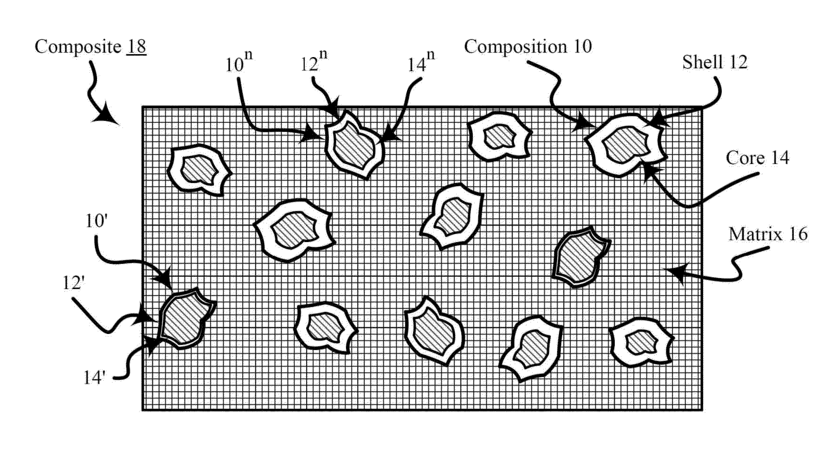
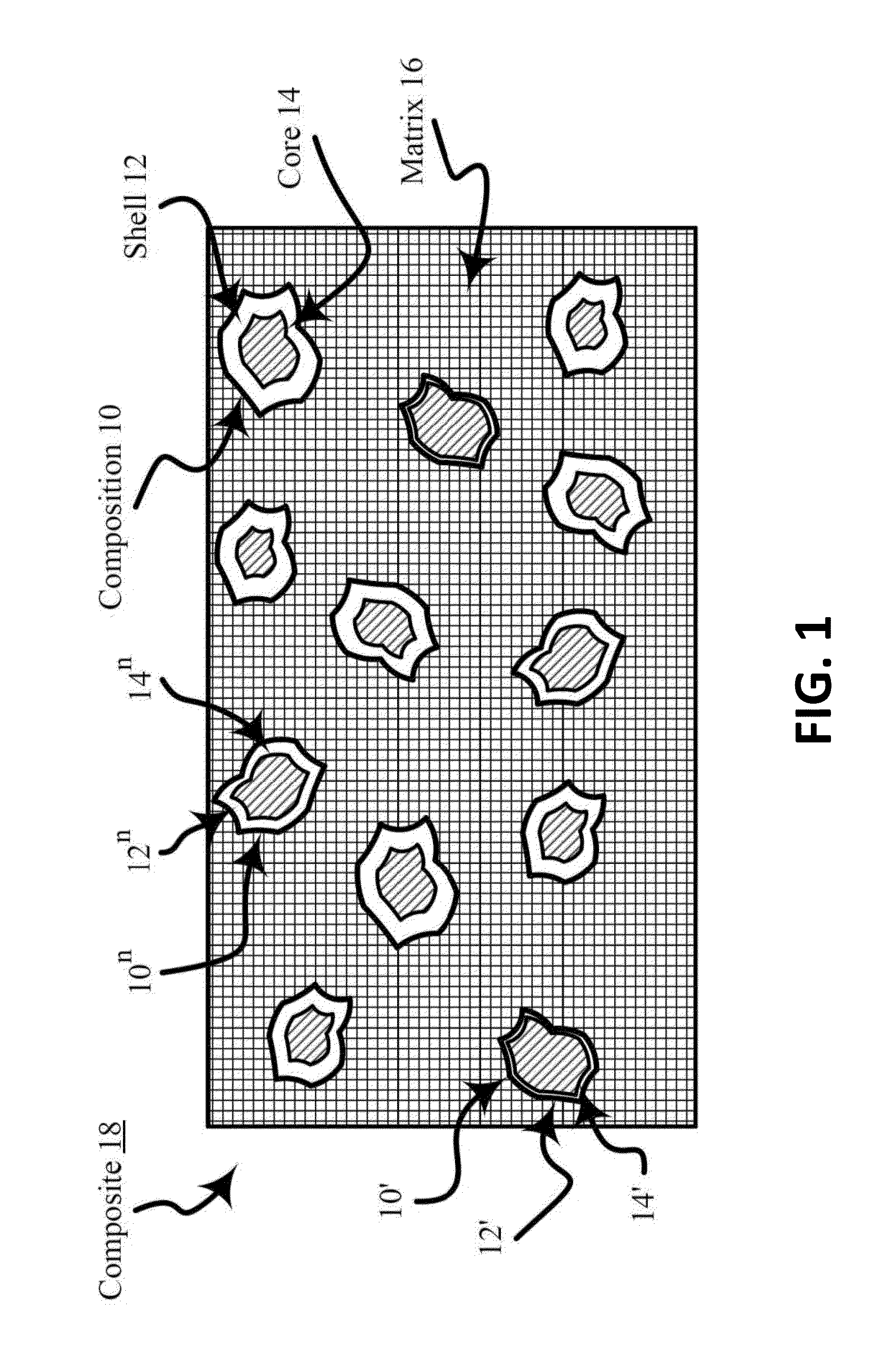
[0104]This Example A relates to a process for a preparation of a composite material of (1) a porous carbon matrix and (2) a composition of nanoparticles including copper and platinum. As described above, the process comprises four (4) stages.

[0105]First stage: A mixture of ingredients is prepared by sequentially adding to about 200 mL of water at about 60° C. while stirring:[0106]from about 5 grams (g) to about 15 g of gelatin GELATIN-B; FLUKA brand and now Sigma-Aldrich Chemie GmbH, Switzerland, cat. No. 48722);[0107]from about 0.5 g to about 2 g of cetyl-trimethyl-ammonium bromide (CTAB-FLUKA brand and now Sigma-Aldrich Chemie GmbH, Switzerland, cat. No. 52365);[0108]from about 5 g to about 20 g of copper acetate (FLUKA brand and now Sigma-Aldrich Chemie GmbH, Switzerland, cat. No. 61145); and[0109]from about 2 g to about 10 g of carbon black (VULCAN® XC72R carbon black, Cabot Corporation headquartered in Boston, Mass., US).

The mixture is homogenized while stirring for ...

example b (

CPC33APtS)

[0121]This Example B relates to a process for a preparation of a composite material of (1) a porous carbon matrix and (2) a composition of nanoparticles including nickel and platinum. As described above, the process might include four (4) stages.

[0122]The process of Example B is substantially that of Example A except that in the First Stage nickel acetate tetrahydrate (FLUKA brand and now Sigma-Aldrich Chemie GmbH, Switzerland, cat. No. 72225) is used instead of copper acetate monohydrate in the preparation of the freeze-dried gel.

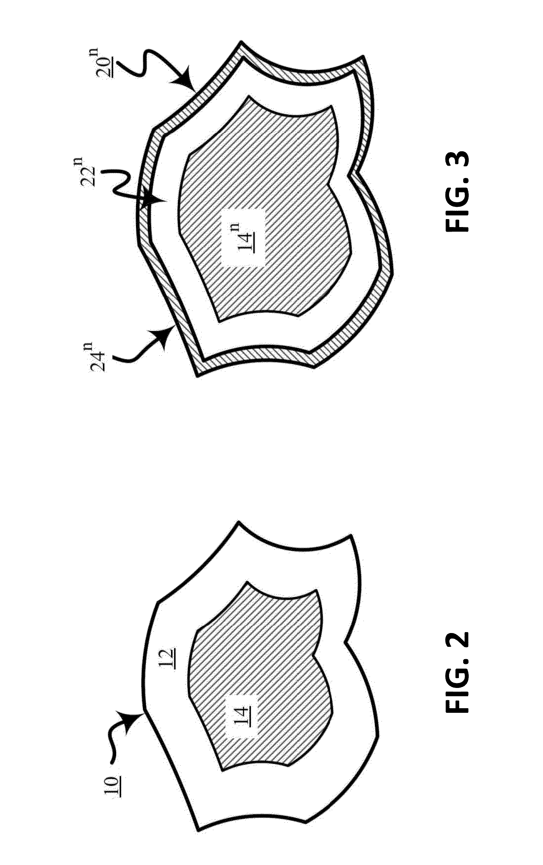
[0123]The heat-treated composite of this Example B includes a porous carbon matrix and nanoparticles including a platinum-nickel alloy coated nickel (e.g., a platinum-nickel alloy shell on a nickel core) and. The platinum-nickel alloy shell on the nickel core is characterized as comprising a non-structured portion (e.g., unarranged Fm 3m structure) and a structured portion (e.g., arranged Pm 3m structure or P4 / mmm structure . . . etc.).

[0124]A sh...

example c (

CPC35APdZ)

[0125]This Example C relates to a process for a preparation of a composite material of (1) a porous carbon matrix and (2) a composition of nanoparticles including copper and palladium. As described above, the process comprises four (4) stages.

[0126]The process of Example C substantially comprises that of Example A except that in the Third stage copper palladization (e.g., covering, treating, and / or combining with palladium or a compound of palladium) is used instead of platinization by using palladium chloride instead of potassium tetrachloroplatinate in the preparation of a composite of a porous carbon matrix and palladiumized nanoparticles including copper.

[0127]The heat-treated composite of this Example C includes a porous carbon matrix and nanoparticles including a palladium-copper alloy coated copper (e.g., a palladium-copper alloy shell on a copper core). The palladium-copper alloy shell on the copper core is characterized as comprising a non-structured portion (e.g....


PUM

PropertyMeasurementUnit
weight percentaaaaaaaaaa
voltageaaaaaaaaaa
temperaturesaaaaaaaaaa

Abstract

Compositions having electrocatalytic activity and composites having electrocatalytic activity, as well as processes for making compositions and composites are described. Also, processes for using such compositions and/or composites, such as, for example, a machine or equipment are described. Some aspects of embodiments and/or embodiments of the present invention are directed to a nanosize transition metal alloy (such as for example an alloy and/or one or more intermetallics comprising copper, cobalt, nickel, palladium, platinum, ruthenium, the like, and combinations thereof) that is electrocatalytically active. Some other aspects of embodiments and/or embodiments of the present invention are directed to a composite material comprising a nanosize transition metal alloy and a carbonaceous matrix.

Description

[0001]This application claims priority to 21 Jul. 2011 by claiming the benefit of U.S. Provisional Patent Application No. 61 / 510,452 entitled “Electrocatalytic Composite(s), Associated Composition(s), and Associated Process(es)” filed on 21 Jul. 2011 in the names of Marjan Bele, Miran Gaber{hacek over (s)}{hacek over (c)}ek, Gregor Kapun, Nejc Hodnik, and Stanko Ha{hacek over (c)}var, which US provisional patent application is herein incorporated by reference in its entirety.FIELD OF INVENTION[0002]Aspects of embodiments and / or embodiments of the present invention generally relate to the field of chemical technology and more specifically to the field of electrocatalysis. Also, aspects of embodiments and / or embodiments of the present invention are directed to one or more of a composition having electrocatalytic activity, a composite material having electrocatalytic activity, a machine or equipment including a composition having electrocatalytic activity, a machine or equipment includ...

Claims


Application Information

Patent Timeline
Patent Type & Authority Applications(United States)
IPC IPC(8): B01J23/89B01J23/00B22F1/054B22F1/17
CPCB22F1/0018Y02E60/523B22F9/22B22F9/30C22C1/05C22C5/04C22C9/00C22C9/06C22C19/03H01M4/921H01M4/926B22F2999/00B22F1/025B82Y30/00Y02E60/50B22F2201/013B22F2201/11B22F1/17B22F1/054B22F1/056
Inventor BELE, MARJANGABERSCEK, MIRANKAPUN, GREGORHODNIK, NEJCHOCEVAR, STANKO
Owner MEBIUS D O O
Why Eureka
Try Eureka