Lightweight bearing and wave gear drive

a technology of wave gear drive and bearing, which is applied in the direction of gearing, liquid/solution decomposition chemical coating, hoisting equipment, etc., can solve the problems of degrading the fixing force and the difficulty of reducing the weight of cross-roller bearings and wave gear drive units

Inactive Publication Date: 2005-11-29
HARMONIC DRIVE SYST IND CO LTD +1
View PDF7 Cites 19 Cited by
  • Summary
  • Abstract
  • Description
  • Claims
  • Application Information

AI Technical Summary

Benefits of technology

[0009]To attain the above object, the present invention provides a lightweight bearing in which at least an outer or inner bearing ring has fixing holes formed therein for fixing the ring to another member, the bearing ring comprising a main bearing ring member in which said fixing holes are formed, and a raceway surface formation member that is fixed to the main bearing ring member and forms a raceway surface on an inner peripheral surface or outer peripheral surface, the raceway surface formation member is formed of an iron-based material, the main bearing ring member is formed of a lightweight material that is lighter than the iron-based material, and a hard plated coating is formed on surface portions of the main bearing ring member that form a seat for fasteners used in the fixing holes.

Problems solved by technology

Moreover, the bearing rings of the cross-roller bearing and rigid internal gear are affixed to other members such as the unit housing, so if such members are made of a lightweight material such as aluminum alloy, the members are not able to withstand the seating pressure of the fixing bolts, leading to seating faces that are defective or strained and the like, thereby degrading the fixing force.
For these reasons, it has been difficult to reduce the weight of cross-roller bearings and wave gear drive units.

Method used


Image

  • Lightweight bearing and wave gear drive
  • Lightweight bearing and wave gear drive
  • Lightweight bearing and wave gear drive

Examples


Embodiment Construction

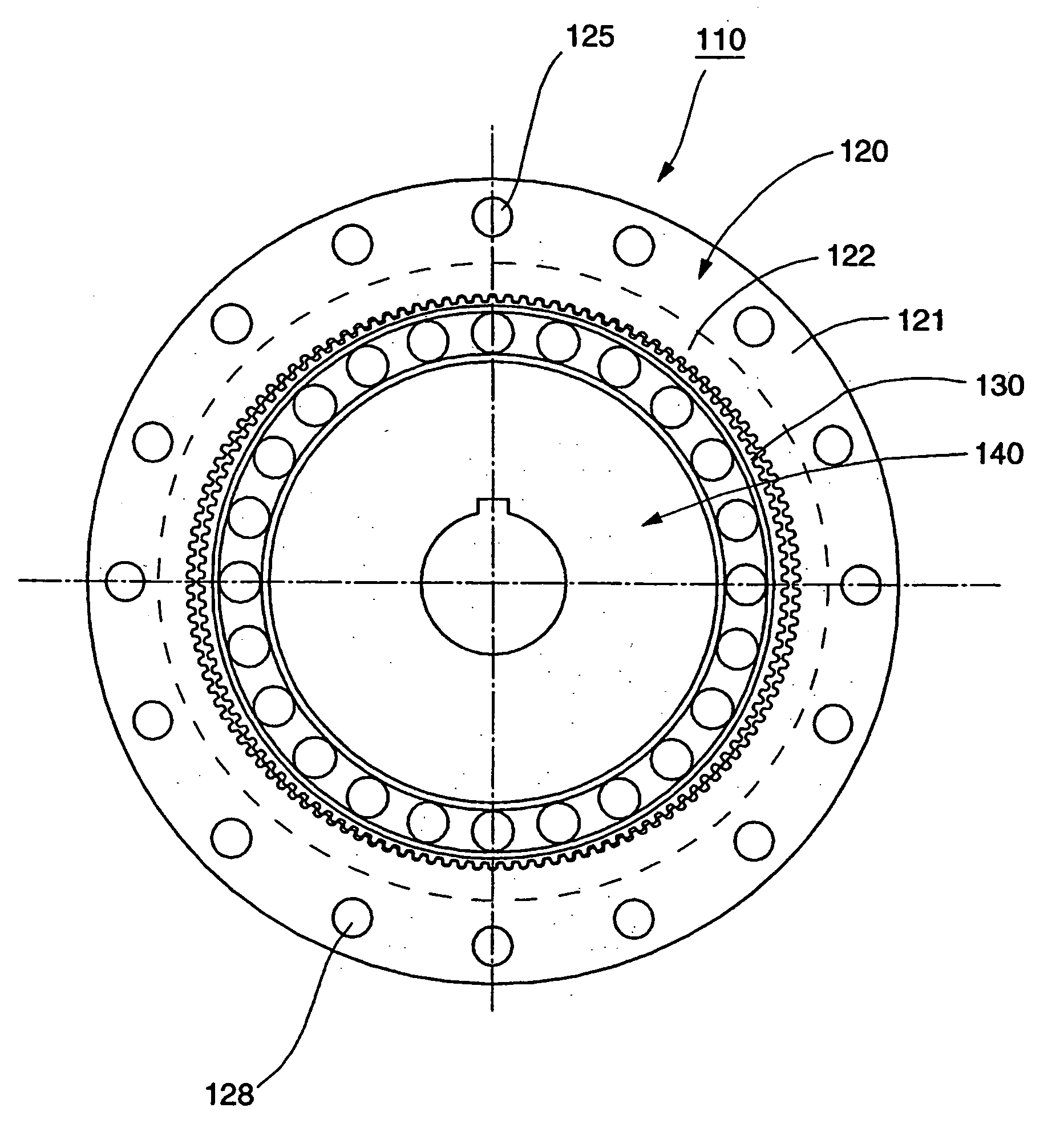
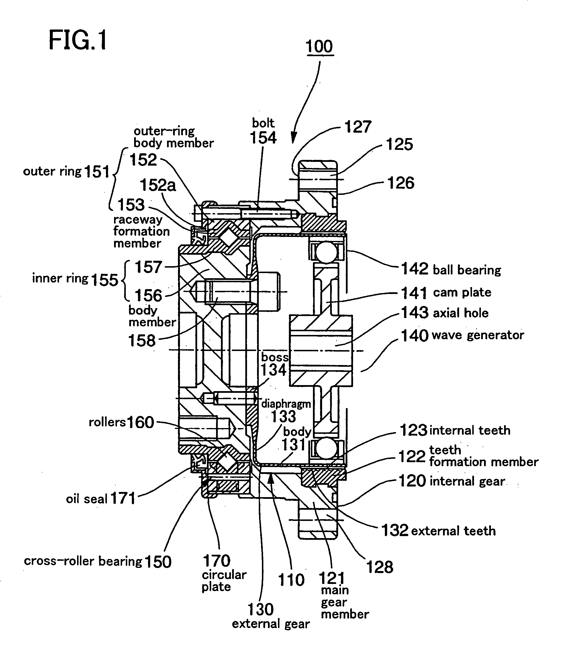
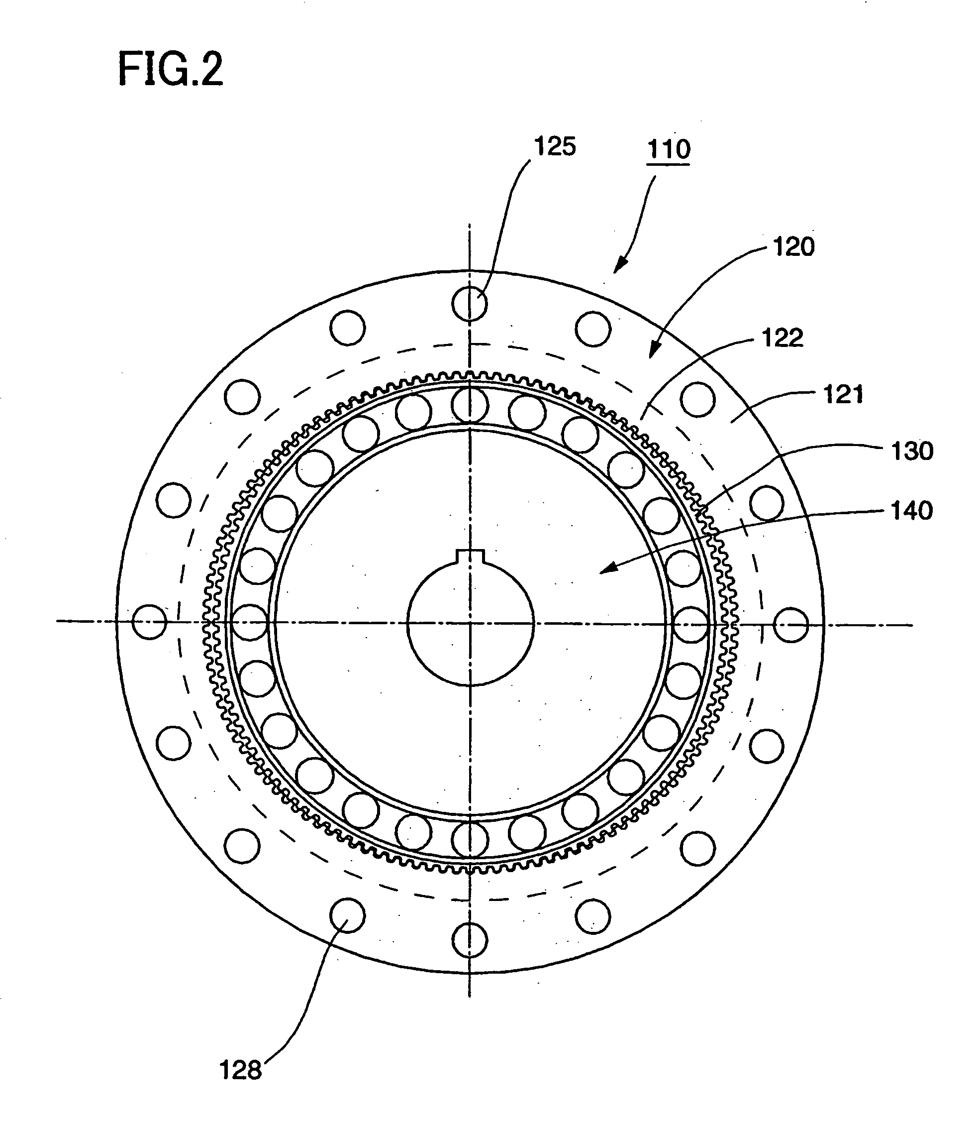
[0021]A wave gear drive unit that applies the present invention will now be described, with reference to FIG. 1, which is a cross-sectional diagram of a cup-shaped wave gear drive unit according to the present invention, and FIG. 2, which shows the configuration of the wave gear drive. The wave gear drive 110 of the wave gear drive unit 100 includes a circular, rigid internal gear 120 having internal teeth 123 provided on its inner peripheral surface, a cup-shaped, flexible external gear 130 disposed inside the rigid internal gear 120, and an elliptical wave generator 140 disposed inside the flexible external gear 130. The flexible external gear 130 and rigid internal gear 120 are rotatably supported by a cross-roller bearing 150 in a way that enables the gears 130 and 120 to rotate relative to each other. The rigid internal gear 120 is a composite part consisting of a cylindrical main gear member 121 and a teeth formation member 122 integrally affixed to an inside peripheral edge o...


PUM

PropertyMeasurementUnit
thicknessaaaaaaaaaa
contact pressureaaaaaaaaaa
thickaaaaaaaaaa

Abstract

A lightweight bearing and wave gear drive are provided. An outer or inner bearing ring of the bearing has fixing holes to enable the ring to be attached to another member. The parts of the bearing on which raceway surfaces are formed are made of an iron-based material, while the main bearing ring member is formed of a lightweight material that is lighter than the iron-based material. Surface portions that constitute fixing bolt seats are plated to increase the strength of such portions. The wave gear drive includes a rigid internal gear, a flexible external gear located inside the internal gear, and a wave generator located inside the external gear. The internal and external gears are coupled by the lightweight bearing in a way that allows the gears to rotate relative to each other.

Description

[0001]This patent application claims the benefit of priority, under 35 U.S.C. §120, as a divisional application of U.S. patent application Ser. No. 10 / 150,962, filed May 21, 2002 now U.S. Pat. No. 6,682,220, entitled “LIGHTWEIGHT BEARING AND WAVE GEAR DRIVE”, hereby incorporated herein by reference, in its entirety.BACKGROUND OF THE INVENTION[0002]1. Field of the Invention[0003]The present invention relates to a lightweight bearing, and to a wave gear drive in which a rigid, circular internal gear and a flexible, circular external gear are coupled by the lightweight bearing so that the gears can rotate relative to each other.[0004]2. Description of the Prior Art[0005]In JP-A 09-250608, now U.S. Pat. No. 6,682,220, this applicant proposed a compact wave gear drive unit that uses a cross-roller bearing. The compact wave gear drive unit of this disclosure included first and second end-plates disposed at each end in the unit's axial direction, a top-hat-shaped wave gear drive incorporat...

Claims


Application Information

Patent Timeline
Patent Type & Authority Patents(United States)
IPC IPC(8): F16C35/063C23C18/31C25D7/00F16C33/62F16C33/64F16C35/067F16H1/32F16H49/00F16H55/17
CPCF16C33/60F16H49/001Y10T74/19Y10S384/912
Inventor KOBAYASHI, MASARUSLATTER, ROLF
Owner HARMONIC DRIVE SYST IND CO LTD
Why Eureka
Try Eureka