Vehicle wheel spoke connection

Active Publication Date: 2011-05-05
SCHLANGER RAPHAEL
View PDF14 Cites 14 Cited by
  • Summary
  • Abstract
  • Description
  • Claims
  • Application Information

AI Technical Summary

Benefits of technology

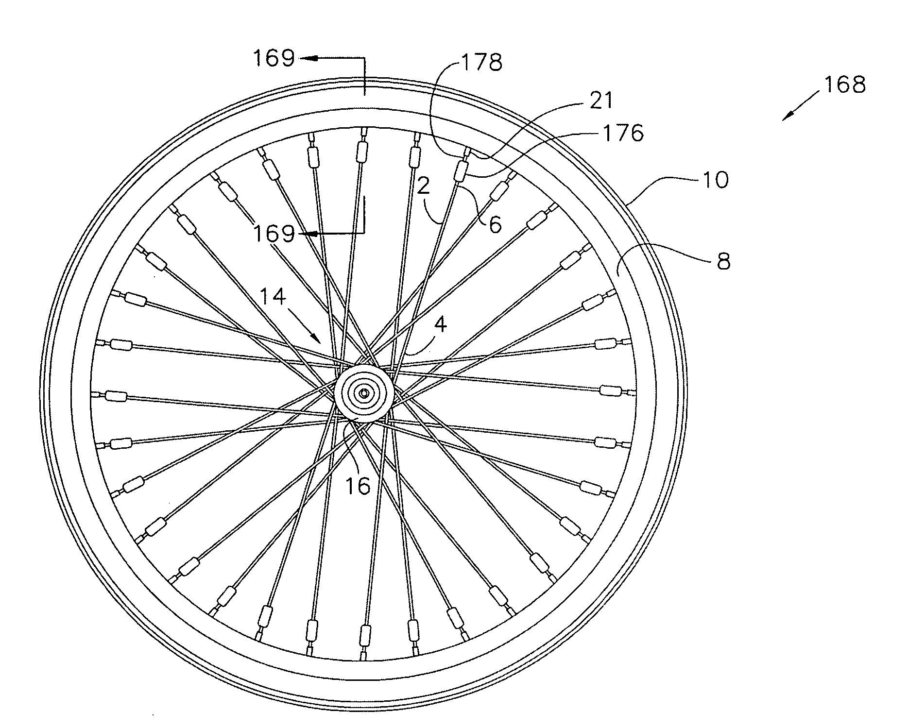
[0021]The embodiments described herein represent a range of configurations wherein an connecting element (i.e. connector) is utilized to create an effective termination or coupling of a tensile element such as a bicycle spoke. The result is an improved assembly, including a means to connect the spoke with a bracing element, such as a hub or rim, to create a bicycle wheel that is exceptionally durable and light in weight.
[0022]The present invention may be readily adapted to lightweight fibrous materials including high-performance fibers, such as carbon fiber, aramid fiber (such as Kevlar®), LCP (liquid crystal fiber such as Vectran®), PBO (polyphenylenebenzobisoxasole) fiber such as Zylon®), polyethylene fiber (such as Spectra®) and the like. These materials may be of the dry-fiber form or they may be impregnated within a matrix. In any case, these materials represent a significant performance improvement over the steel spokes they replace. In comparison with the steel wire commonly used in spoke construction, these fibrous materials have equivalent or greater tensile strength than the steel spoke at a much lower density. This allows for th

Problems solved by technology

However, the steel spokes of conventional bicycle wheels are quite heavy and add significant weight to the wheel assembly.
In addition to their excessive weight, steel bicycle spokes have poor vibration-damping characteristics and tend to be very efficient at transmitting road vibration to the rider.
By transmitting vibration, rather than absorbing it, the conventional steel-spoke bicycle wheel lacks in rider comfort and control.
This causes the stress in the spoke to increase and makes the wheel more prone to spoke failure due to fatigue.
However, when attempting to u

Method used


Image

  • Vehicle wheel spoke connection
  • Vehicle wheel spoke connection
  • Vehicle wheel spoke connection

Examples


Embodiment Construction

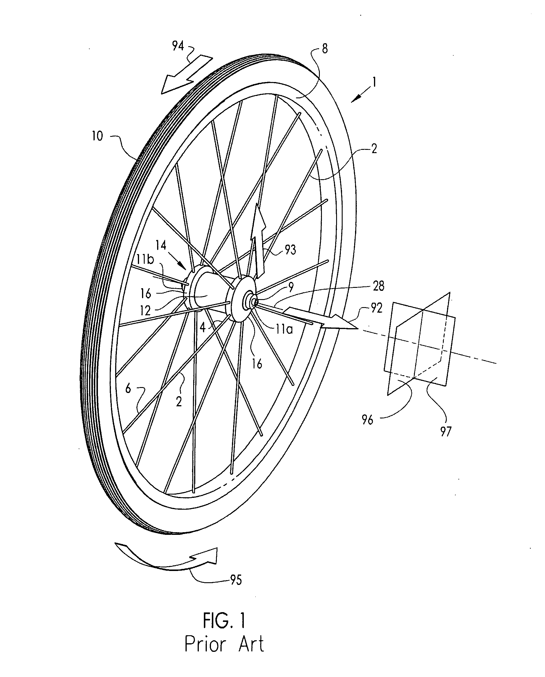
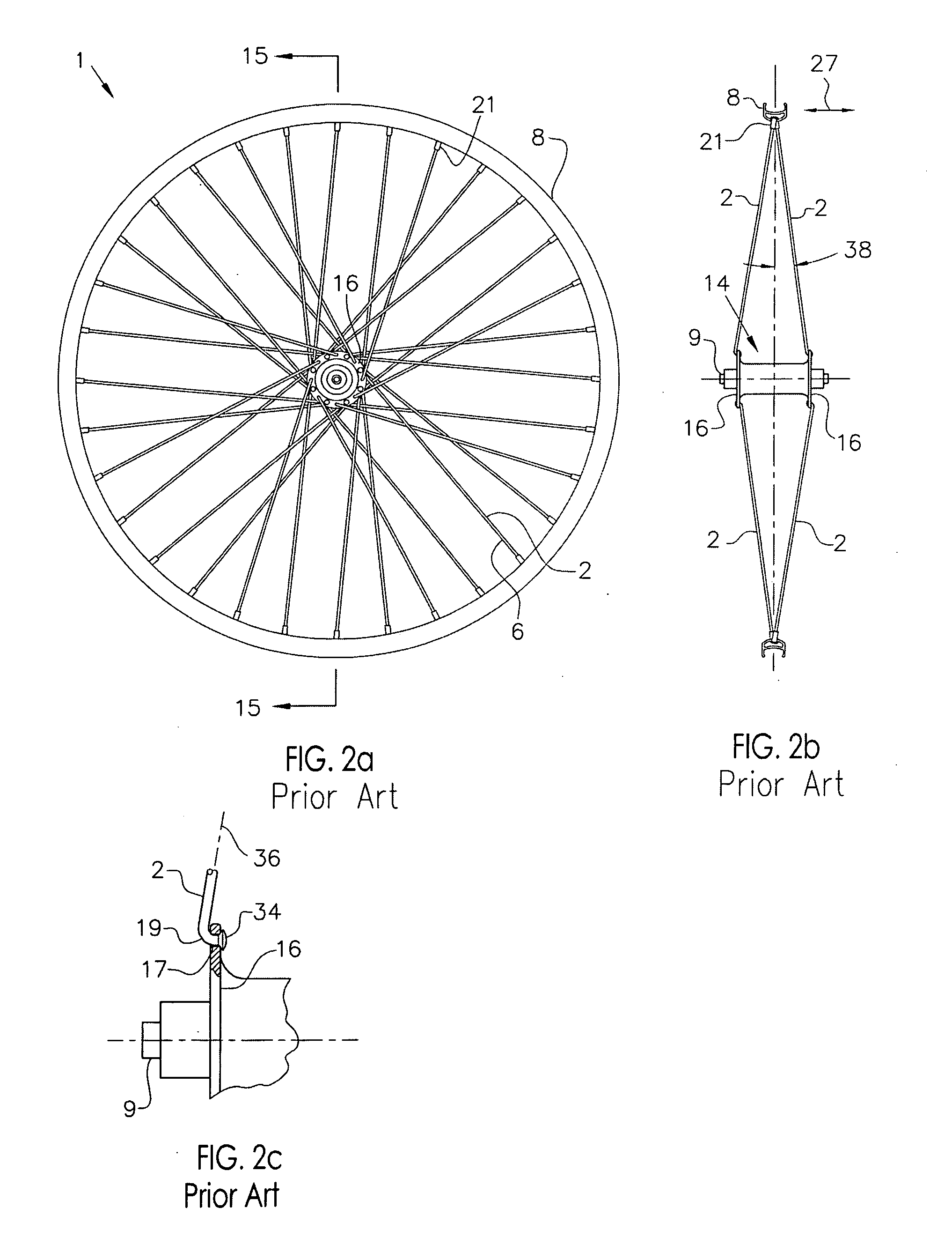
[0068]FIG. 1 describes the basic configuration of an exemplary prior art vehicle wheel, in particular, a bicycle wheel 1, as well as a description of the direction conventions used throughout this disclosure. For clarity, the bicycle frame and the quick release skewer assembly are not shown in this figure. The hub shell 14 is rotatable about the axle 9 and includes at least two axially spaced hub flanges 16, each of which include a means for connecting with the spokes 2. Axle 9 includes end faces 11a and 11b that define the spacing of its mounting with the frame (not shown). The axial axis 28 is the axial centerline of rotation of the bicycle wheel 1. The hub flange 16 may be contiguous with the hub shell 14 or it may be separately formed and assembled to the hub body 12 portion of the hub shell 14. The spokes 2 are affixed to the hub flange 16 at their first end 4 and extend to attach the rim 8 at their second end 6. The tire 10 is fitted to the outer periphery of the rim 8. The wh...


PUM


Abstract

An improved vehicle wheel, including a rim, a hub with a central axle and an outer flange, a plurality of spokes extending between the rim and hub and a connecting element connected to at least one of the spokes. The spoke is a generally slender element with a longitudinal axis with a span portion between the rim and hub and a tensile axis of applied tensile load along the span portion. At least one of said rim and hub constitutes a bracing element. The connecting element includes an external surface and an internal cavity with an internal surface adjacent said spoke. The connecting element is joined to the spoke by means of a crimped joinder such that said external surface is pressed inwardly to plastically deform said connecting element to displace the internal surface toward the spoke. The crimped joinder supports tensile load through an engagement interface.

Description

CROSS-REFERENCE TO RELATED APPLICATION[0001]This application is a Continuation-In-Part of U.S. patent application Ser. No. 12 / 806,064, filed Aug. 5, 2010, which is a Continuation-In-Part U.S. patent application Ser. No. 11 / 879,333, filed Jul. 17, 2007 and issued as U.S. Pat. No. 7,784,878, which is a Continuation-In-Part of U.S. patent application Ser. No. 10 / 755,653, filed Jan. 12, 2004 and issued as U.S. Pat. No. 7,357,460.BACKGROUND OF THE INVENTION[0002](1) Field of the Invention[0003]The present invention relates to an improved connection system for a vehicle wheel spokes, particularly applicable to the spoke of a bicycle wheel.[0004](2) Description of the Related Art[0005]Heretofore, the vast majority of bicycle wheels have been constructed using steel wire spokes with one headed end for connection with the bicycle hub and an opposing end that is directly threaded to accept a spoke nipple that engages the rim. By adjusting the threaded connection between the spoke and the nipp...

Claims


Application Information

Patent Timeline
IPC IPC(8): B60B1/04B60B1/14B60B5/02
CPCB60B1/003B60B1/0261B60B1/041B60B1/042B60B31/02B60B21/025B60B21/062B60B21/064B60B1/044
Inventor SCHLANGER, RAPHAEL
Owner SCHLANGER RAPHAEL
Why Eureka
Try Eureka