Circulating fluidized bed boiler and a method of assembling a circulating fluidized bed boiler

a fluidized bed and boiler technology, applied in the direction of fluidised bed combustion apparatus, combustion types, lighting and heating apparatus, etc., can solve the problems of increasing the cross-sectional area, reducing the efficiency of combustion, and increasing the difficulty of circulating fluid, so as to reduce the risk of circulating fluid evaporation, and reduce the effect of circulating fluid

Active Publication Date: 2019-12-10
SUMITOMO SHI FW ENERGIA OY
View PDF11 Cites 0 Cited by
  • Summary
  • Abstract
  • Description
  • Claims
  • Application Information

AI Technical Summary

Benefits of technology

[0018]The vertical outlet tubes of the particle separators direct the flue gas streams upwards, whereafter, the flue gas streams have to turn ninety degrees, to the horizontal direction, to flow in the horizontally extending cross over duct system towards the back pass. An advantage of the present invention is that the flue gas streams can flow in the cross over duct system all the way to an opening in the first back pass wall along a straight path, without additional bends. The first back pass wall is generally perpendicular, or at least nearly perpendicular, to each of the long walls of the furnace, and the first and second gas flow directions are advantageously mirror symmetrically inclined to the sidewalls of the furnace.
[0019]According to a preferred embodiment of the present invention, each of the first and second duct structures is constructed as an open box, without partition walls. Due to the shape and construction of the duct structures, the flue gas flows in each of the first and second duct structures as a combined, single stream formed of multiple initial streams originating from the respective particle separators. More particularly, a first combined flue gas stream flows in the first duct structure in the first gas flow direction, and a second combined flue gas stream flows in the second duct structure in the second gas flow direction.
[0020]Each of the first and second duct structures preferably has a constant height, due to bottom and top walls at a constant level, and a width that increases stepwise, at connection points of the gas outlet tubes of the particle separators, in the respective flue gas flow direction. Due to the increasing cross-sectional area, the velocity of the flue gas remains approximately constant throughout the cross over ducts. Such a constant velocity renders possible a smooth flow of the flue gas without excessive turbulence and minimized erosion caused by particles entrained with the gas flow.
[0021]The cross over duct system is preferably cooled, i.e., it comprises water or steam tubes for transferring heat from the flue gas to water or steam. More particularly, the cross over duct system has a relatively simple shape that can be manufactured economically, and is advantageously made of straight water tube panels, to obtain a durable and light weight construction. Preferably, the cooled cross over duct system is internally protected, in order to further minimize erosion, by a refractory layer.
[0022]The first back pass wall is advantageously symmetrical about a vertical center line, the first openings, forming a first inlet opening area, and the second openings, forming a second opening area, being located on the respective sides of the vertical center line, at an upper section of the first back pass wall. According to a preferred embodiment of the present invention, each of the first and second opening areas comprises multiple substantially evenly distributed openings, and the first and second inlet opening areas together cover a portion of the first back pass wall that extends over most of the horizontal width of the first back pass wall. Due to the shape of the cross over duct system and the distribution of openings in the first back pass wall, the cross over duct system provides especially uniform distributions of temperature and velocity of the flue gas in the back pass. Thereby, the cross over duct system enables especially efficient and reliable heat recovery in the back pass.
[0023]According to a preferred embodiment of the present invention, the first back pass wall is planar and parallel to the second short sidewall of the furnace, whereby the first and second opening areas are on a plane having a normal direction that is inclined to the first and second gas flow directions. According to another preferred embodiment of the present invention, the first opening area is on a first planar wall portion and the second opening area is on a second planar wall portion, which first and second wall portions are horizontally adjacent to each other, and have different normal directions. Especially, each of the first and second wall portions has a central edge and an outermost edge, wherein the central edges are closer to the second short sidewall of the furnace than the outermost edges. According to a preferred embodiment, the first and second wall portions have a common central edge. The normal directions of the first and second wall portions preferably make an angle with the respective first and second gas flow directions that is smaller than it would be with a planar first back pass wall described above. Even more preferably, the angle is zero, i.e., the normal directions of the first and second wall portions are parallel to the first and second gas flow directions, respectively.

Problems solved by technology

Thus, the gas flow becomes, especially, at the final sections of a flue gas collecting duct, very high, and potentially eroding, unless the diameter or height of the flue gas duct increases towards the end.
Such gradually widening flue gas ducts are, however, usually relatively complicated constructions.
Such a construction increases the weight of the main flue gas collecting ducts and may cause problems due to the non-constant velocity of the flue gas flow.

Method used


Image

  • Circulating fluidized bed boiler and a method of assembling a circulating fluidized bed boiler
  • Circulating fluidized bed boiler and a method of assembling a circulating fluidized bed boiler
  • Circulating fluidized bed boiler and a method of assembling a circulating fluidized bed boiler

Examples


Embodiment Construction

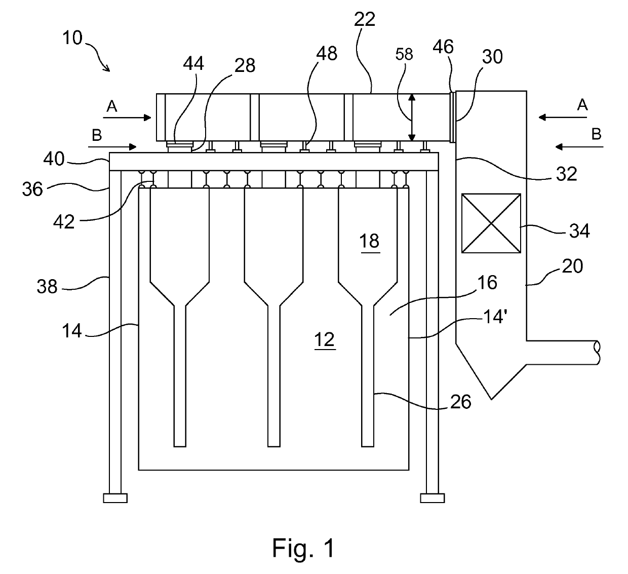
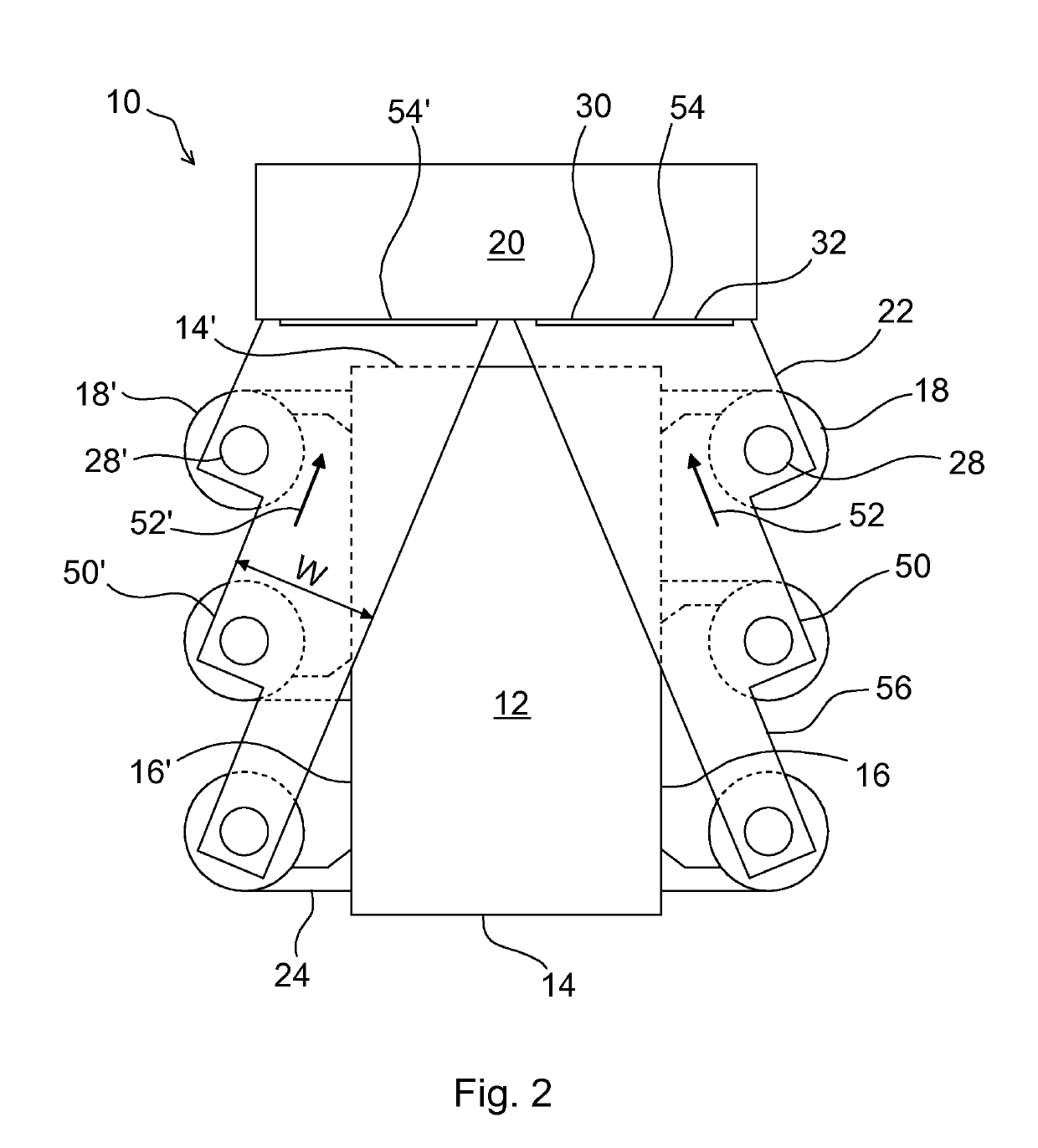
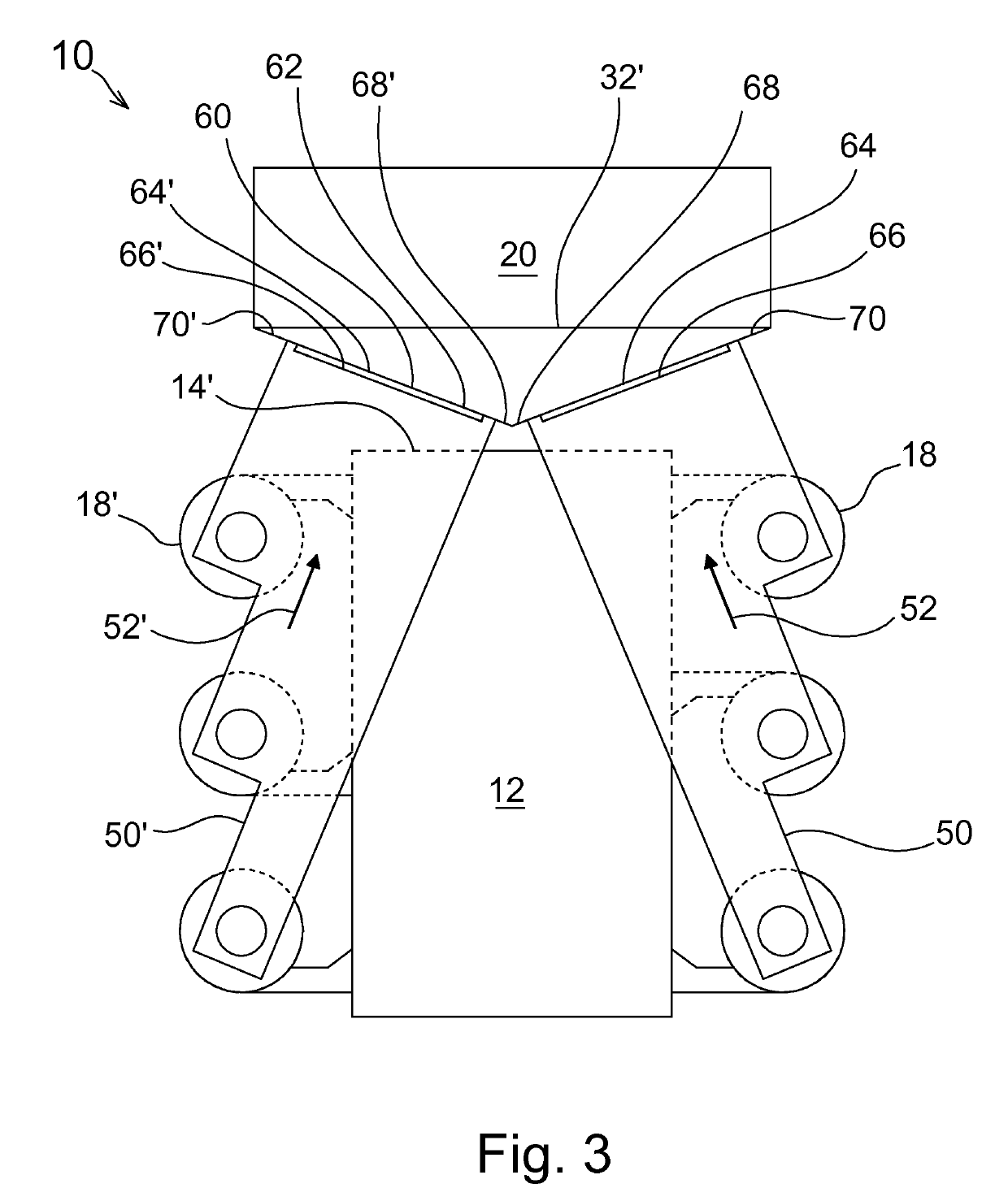
[0032]FIG. 1 shows a schematic side view of a circulating fluidized bed (CFB) boiler 10 in accordance with a preferred embodiment of the present invention. The furnace 12 of the CFB boiler 10 has a rectangular cross section, having first and second short sidewalls 14, 14′ and first and second long sidewalls 16, only one of which is seen in FIG. 1. Multiple particle separators 18 are connected to each of the long sidewalls 16 of the furnace 12. The number of particle separators 18 on each long sidewall 16 is, here, three, but it could also be, for example, two, or four. The particle separators 18 are in flow connection with a back pass 20 arranged on the second short sidewall 14′ of the furnace 12 by a horizontally extending cross over duct system 22. In the following, the same reference numbers are generally used for the same elements in different Figures.

[0033]When fuel is combusted in the furnace 12, hot flue gas and particles entrained therewith are discharged through flue gas di...


PUM


Abstract

A circulating fluidized bed boiler includes a rectangular furnace, which is horizontally enclosed by sidewalls, for combusting fuel and combustion gas and generating a stream of flue gas and particles. The sidewalls include first and second short sidewalls and first and second long sidewalls. Multiple particle separators are arranged on the side of each of the first and second long sidewalls for separating particles from the stream of flue gas and particles discharged from the furnace. Each of the particle separators includes a vertical gas outlet tube for discharging cleaned flue gas from the particle separator. A back pass arranged on the side of the second short sidewall of the furnace is horizontally enclosed by back pass walls. A horizontally extending cross over duct system is directly connected to the vertical gas outlet tubes of the particle separators for conducting the cleaned flue gas to the back pass.

Description

CLAIM OF PRIORITY[0001]This application is a U.S. national stage application of PCT International Application No. PCT / FI2017 / 050197, filed Mar. 22, 2017, which claims priority from Finnish Patent Application No. 20165287, filed Apr. 4, 2016.FIELD OF THE INVENTION[0002]The present invention relates to a circulating fluidized bed (CFB) boiler, and, more specifically, relates to a CFB boiler comprising a rectangular furnace that is horizontally enclosed by first and second long sidewalls and by first and second short sidewalls, a back pass arranged on the side of the second short sidewall, multiple particle separators arranged on the side of each of the first and second long sidewalls, each of the particle separators comprising a vertical gas outlet tube for discharging cleaned flue gas from the particle separator, and a horizontally extending cross over duct system connected to the gas outlet tubes of the particle separators for conducting the cleaned flue gas to the back pass.BACKGRO...

Claims


Application Information

Patent Timeline
Patent Type & Authority Patents(United States)
IPC IPC(8): F23C10/10F23J11/00F23M5/08
CPCF23J11/00F23M5/08F23C10/10F23J2211/00F22B31/0084F22B31/0007
Inventor LANKINEN, PENTTI
Owner SUMITOMO SHI FW ENERGIA OY
Why Eureka
Try Eureka