Circulating Fluidized Bed Boiler

a fluidized bed and boiler technology, applied in steam boiler components, combustion process, lighting and heating apparatus, etc., can solve the problems of high gas flow, complex construction, and high potential eroding of the flue gas duct, and achieve the effect of increasing the cross section, reducing the cost of manufacturing a cooled flue gas system, and reducing the cost of production

Active Publication Date: 2012-03-22
FOSTER WHEELER ENERGIA OY
View PDF15 Cites 1 Cited by
  • Summary
  • Abstract
  • Description
  • Claims
  • Application Information

AI Technical Summary

Benefits of technology

[0018]The increase of the cross section is advantageously made by keeping the top surface of the duct at a constant level, and increasing the height of the duct downwards at the point where the gas flow from the back separator merges with that from the front separator. Thus, between the front separator and the back separator, i.e., above the furnace, there is a free space, which can be advantageously used, for example, for arranging suspension means for heat exchangers within the furnace.
[0019]The flue gas ducts are advantageously made of straight water tube panels, which are bent in a suitable manner to obtain the required shape, especially, at the point where the gas flow from the back separator merges with that from the front separator. A cooled flue gas duct system is advantageous as a durable and light weight construction. The making of simple-shaped cross over ducts, according to the present invention, thus renders it possible to manufacture a cooled flue gas system economically, by using straight water tube panels.
[0020]Due to the use of only one increasing section, instead of, for example, two or three increasing sections required in a corresponding flue gas duct connecting three or four particle separators on a long sidewall, a relatively smooth flow of the flue gas can be obtained in the cross over ducts according to the present invention. The junction of the flue gas flows form a back separator and from the corresponding front separator is directed at the junction to be aligned with the flow from the front separator. By this arrangement, the flue gases flow smoothly through the flue gas duct system without a high pressure drop or heavy turbulence, which might cause high erosion at the internal surfaces of the systems due to remaining fly ash entrained with the flue gas.
[0021]Cooled flue gas duct systems are conventionally internally protected, in order to avoid erosion, by a refractory layer. However, due to the simple and optimized shape of the cross over ducts according to the present invention, at least a portion of the duct system is advantageously not protected by a refractory layer, but the flue gas is allowed to contact the metal surface of the water or steam tube panels of the cross over ducts. Thereby, the manufacturing costs of the cross over ducts are decreased and the heat transfer rate at the surfaces is improved.
[0022]The back pass has advantageously a rectangular cross section with a first long sidewall facing the back wall and two short sidewalls being parallel to the short sidewalls of the furnace. Thereby, all cross over ducts may be connected to the upper portion of the first long sidewall of the back pass. However, according to a preferred embodiment of the present invention, which is especially useful when there are at least four cross over ducts, the two centermost cross over ducts are connected to the first long sidewall, but the two outermost cross over ducts are connected by a bending channel to the upper portion of the short sidewalls of the back pass. This construction renders it possible to arrange an identical pillars system for supporting all the main support beams. By this construction, it is also possible to obtain an even flow of flue gas to the back pass, which improves the heat transfer efficiency in the heat exchange surfaces in the back pass.

Problems solved by technology

Thus, the gas flow becomes, especially at the final sections of a flue gas duct, very high, and potentially eroding, unless the cross section of the flue gas duct increases towards the end.
Such gradually widening flue gas ducts are, however, complicated constructions.
Such construction increases the weight of the flue gas ducts and may cause problems due to the non-constant velocity of the flue gas flow.
This arrangement provides a complicated construction, which is, for example, difficult to support.

Method used


Image

  • Circulating Fluidized Bed Boiler
  • Circulating Fluidized Bed Boiler
  • Circulating Fluidized Bed Boiler

Examples


Embodiment Construction

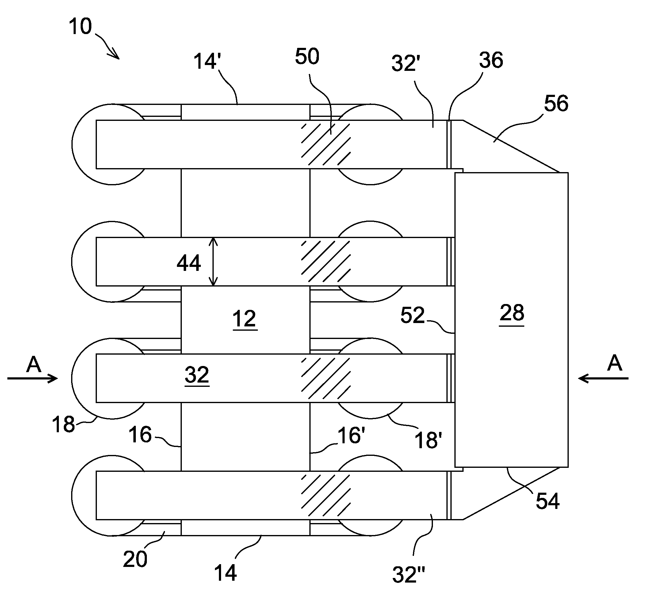
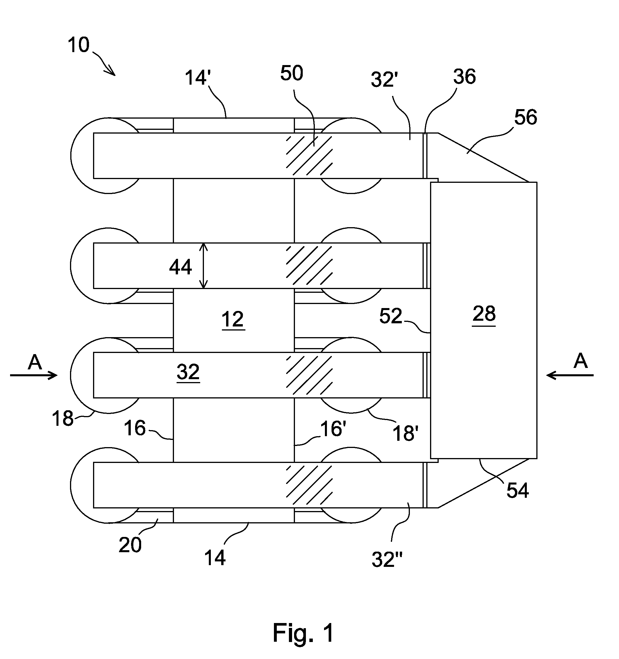
[0026]FIG. 1 shows a schematic top view of a circulating fluidized bed (CFB) boiler 10 in accordance with the present invention, and FIG. 2 shows a schematic vertical cross-sectional view of the CFB boiler, taken along line A-A of FIG. 1. The furnace 12 of the CFB boiler has a rectangular cross section, having two short sidewalls 14, 14′ and two long sidewalls, the front wall 16 and the back wall 16′. Multiple particle separators 18, 18′ are connected by flue gas discharge channels 20 to each of the long sidewall. The number of particle separators on each long sidewall is here four, but it could also be, for example, three, or even more than four.

[0027]When fuel is combusted in the furnace 12, hot flue gas and particles entrained therewith are discharged through the flue gas discharge channels 20 to the particle separators 18, 18′. Particles separated from the flue gas in the particle separator 18, 18′ are returned back to the lower portion of the furnace 12 via return ducts 22. The...


PUM


Abstract

A circulating fluidized bed boiler includes a rectangular furnace which is horizontally enclosed by a front wall, a back wall and two sidewalls, and multiple particle separators connected to the upper portion of each of the front wall and the back wall. Each particle separator includes a gas outlet, and flue gas duct system connected to the gas outlets for conducting cleaned flue gas to a back pass. The particle separators are arranged in pairs of particle separators. Each pair of particle separators includes a front separator arranged adjacent to the front wall and a back separator arranged adjacent to the back wall. The flue gas duct system includes cross over ducts, each cross over duct connecting the gas outlet of a front separator of a pair of particle separators, across and over the furnace, to the gas outlet of the back separator of the same pair of particle separators, and to the back pass, which back pass is arranged on the back wall side of the furnace.

Description

[0001]This application is a U.S. national stage application of PCT International Application No. PCT / FI2010 / 050281, filed Apr. 8, 2010, published as PCT Publication No. WO 2010 / 116039 A1, and which claims priority from Finnish patent application number 20095399, filed Apr. 9, 2009.FIELD OF THE INVENTION[0002]The present invention relates to a circulating fluidized bed (CFB) boiler, and more particularly, the present invention relates to a large CFB boiler typically having a capacity of more than about 300 MWe, and comprising multiple particle separators connected in parallel to each of the two long sidewalls of the furnace. The invention is particularly directed to the arrangement of a flue gas duct system, which is used for conducting cleaned flue gas from the particle separators to a back pass.[0003]Streams of flue gas and solid particles entrained therewith are generally discharged from the furnace of a large CFB boiler through flue gas discharge channels to multiple particle sep...

Claims


Application Information

Patent Timeline
Patent Type & Authority Applications(United States)
IPC IPC(8): F22B37/48
CPCF23C10/10F22B31/00F23C10/08
Inventor LANKINEN, PENTTIKAUPPINEN, KARIKINNUNEN, PERTTI
Owner FOSTER WHEELER ENERGIA OY
Why Eureka
Try Eureka