Cutting head for cutting a food product

Active Publication Date: 2005-11-29
URSCHEL LAB
View PDF11 Cites 97 Cited by
  • Summary
  • Abstract
  • Description
  • Claims
  • Application Information

AI Technical Summary

Benefits of technology

[0012]According to the principles of the present invention, these features of the cutting head of the present invention improve the precision of the adjustability of the gate opening since the pivot pins are positioned closely adjacent the forward edge of the cutter support segments, and substantially near the cutting edge of the cutting blades. This results in reducing the excursion of the cutting edge to the adjacent cutter support segment relative to adjustment by the adjustment mechanism over the known cutting head. Furthermore, the portion of the c

Problems solved by technology

It has been found with the known cutting head that it is difficult and time consuming to precisely adjust the gate openings to a desired width, and thereby produce slices or shreds of uniform thickness.
It follows that it is also difficult to achieve a uniform gate opening between each cutting blade and an adjacent rear edge of a cutter support segment, and it has been found that the known cutting head will yield an inconsistent slice or shred thickness about the circular array of cutter support segments for a given cutting operation.
The problem associated with the known cutting heads stems in large pat from the location of the pivot pins relative to the cutting edge of the cutting blade, and with the configuration of the known cutter support segments, the pivot pin locations could not be brought closer to the cutting edge of the cutting blade to improve the geome

Method used


Image

  • Cutting head for cutting a food product
  • Cutting head for cutting a food product
  • Cutting head for cutting a food product

Examples


Example

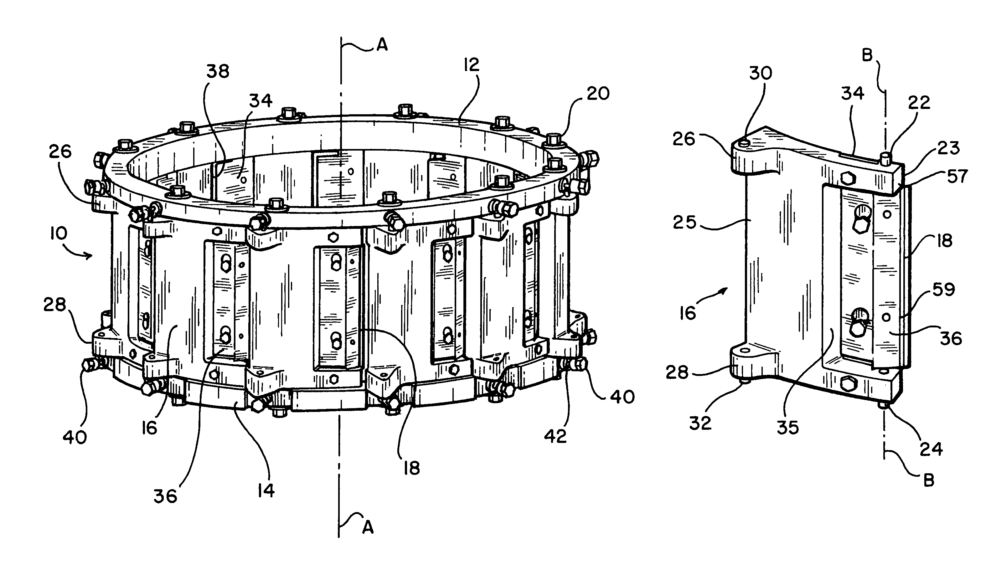
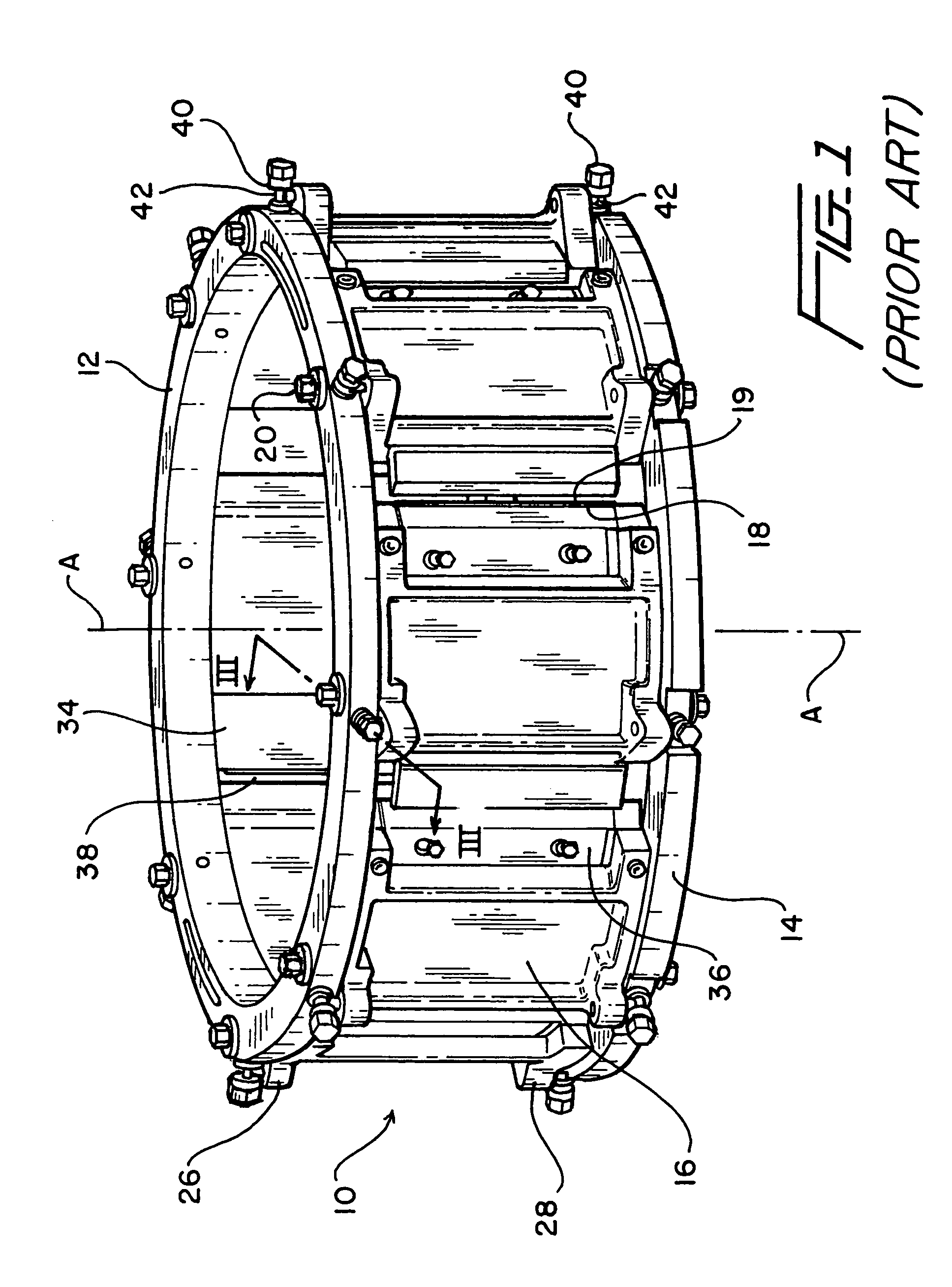
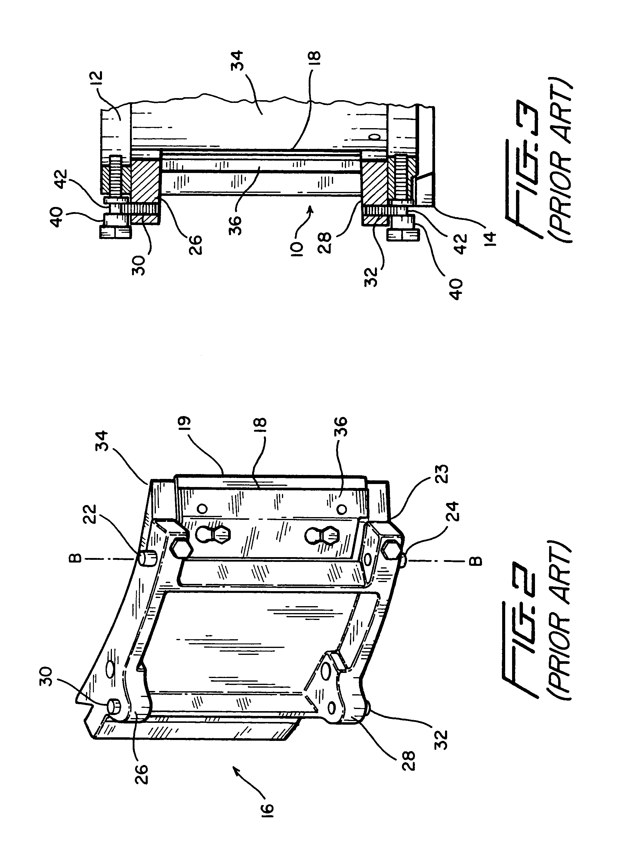
[0024]With reference now to the drawings, FIG. 1 illustrates a cutting head 10 for a food product cutting machine that is well known in the art and is at least in part further described in U.S. Pat. No. 5,694,824, the entirety of which is incorporated herein by reference. The cutting head 10 includes upper and lower mounting rings 12, 14 between which are mounted a plurality of cutter support segments 16, each having a cutting blade 18 mounted thereon. As can be seen, the cutter support segments 16 are arranged in a generally circular, annular array about axis A—A, and have inner and outer sides relative to the interior and exterior of the circular, annular array. The inner surfaces of the cutter support segments 16 define a central portion of the cutting head 10 that includes a circumference defined by the circular array of cutter support segments 16. Each of the cutter support segments 16 are attached to both the upper and lower mounting rings 12, 14 by a plurality of fastening de...


PUM

PropertyMeasurementUnit
Fractionaaaaaaaaaa
Angleaaaaaaaaaa
Sizeaaaaaaaaaa

Abstract

An improved cutting head for a food product on a slicing machine including upper and lower mounting rings, a plurality of cutter support segments connected to the mounting rings, a cutting blade attached to a front edge portion of each cutter support segment, and opposed first and second pivot pins extending from upper and lower portions of the cutter support segment and through the upper and lower mounting rings. Each of the pivot pins are positioned at a location closely adjacent to a forward edge of the cutter support segment and substantially near a cutting edge of the cutting blade.

Description

[0001]This application claims the benefit of provisional application No. 60 / 473,888 filed May 29, 2003.BACKGROUND OF THE INVENTION[0002]1. Field of the Invention[0003]The present invention relates to an improved cutting head for a food product slicing machine.[0004]2. Discussion of Related Art[0005]Machines for slicing or cutting food products, such as vegetables, nuts, and fruit, are well known in the art. A known slicing apparatus is described in U.S. Pat. No. 5,694,824 and comprises a main frame, a drive motor, a stationary annular cutting head fixedly attached to the main frame and having a series of circumferentially spaced cutter support segments each with a cutting blade having a cutting edge mounted thereon, and a rotatable impeller surrounded by the cutting head and connected to a drive motor for rotation within the cutting head. The cutting head and the impeller are configured so that the impeller directs a food product outwardly against the cutting blades when the impelle...

Claims


Application Information

Patent Timeline
IPC IPC(8): B26D1/36B26D7/26
CPCB26D1/03B26D7/0691B26D7/2614B26D7/2628Y10S83/932Y10T83/6473Y10T83/9372Y10T83/9408Y10T83/9488
Inventor KING, DANIEL W.
Owner URSCHEL LAB
Why Eureka
Try Eureka