Steering control during split-mu ABS braking

Inactive Publication Date: 2005-11-29
TRW LIMITED
View PDF12 Cites 44 Cited by
  • Summary
  • Abstract
  • Description
  • Claims
  • Application Information

AI Technical Summary

Benefits of technology

[0006]It is one object of the present invention to provide a means which will maintain the vehicle stable and controllabl

Problems solved by technology

In the latter conditions, where a split mu braking operation is taking place, the unbalanced braking

Method used


Image

  • Steering control during split-mu ABS braking
  • Steering control during split-mu ABS braking
  • Steering control during split-mu ABS braking

Examples


Embodiment Construction

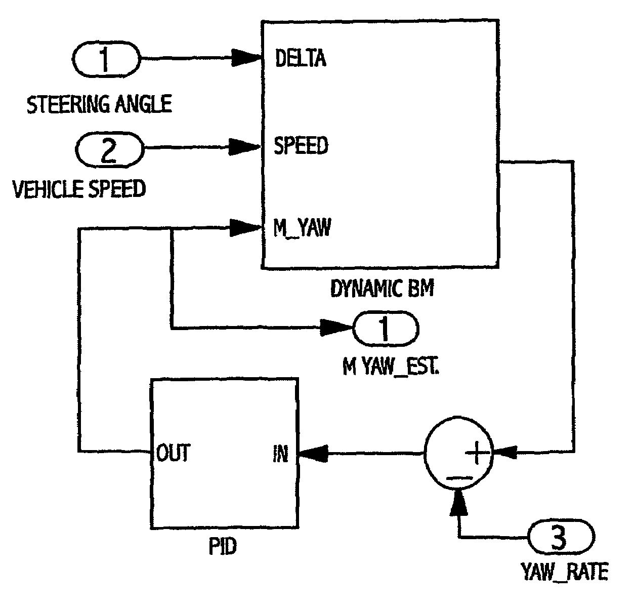
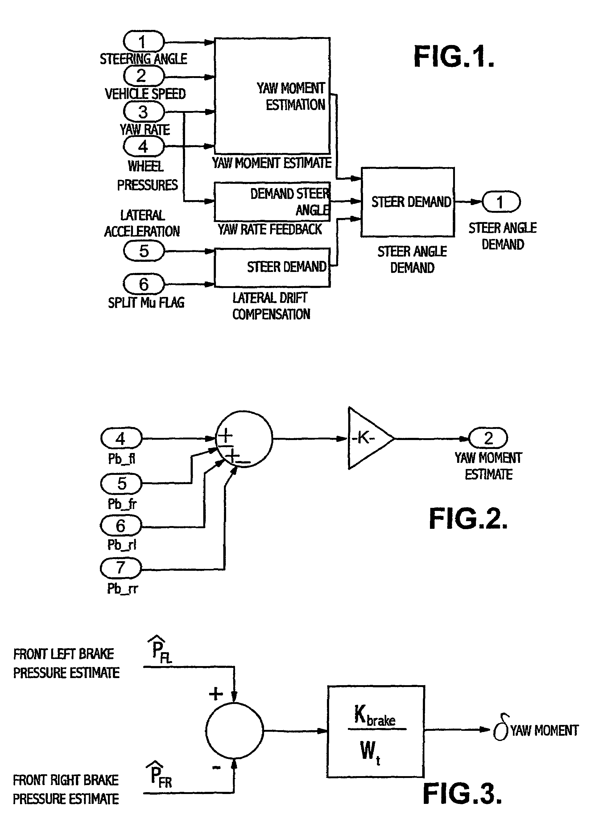
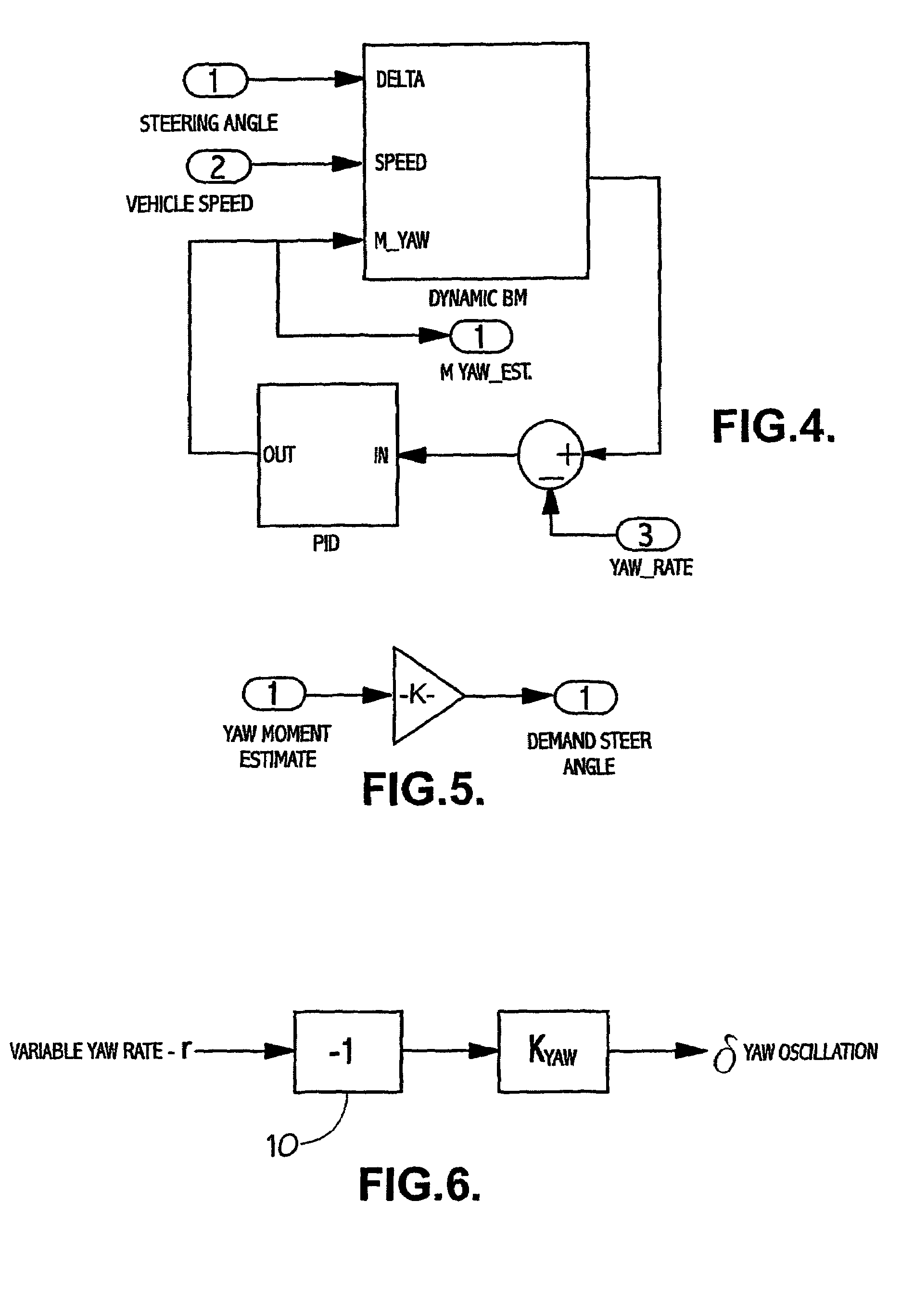
[0041]The present technique involves the generation of one or more variables representing corrective steer angle demands for the vehicle which is / are supplied to a “driver feedback” controller to produce an output signal for modifying the EAS assistance torque.

Steer Angle Demand

[0042]These operational variables required to produce the steer angle demand are:[0043]a) Yaw Moment Estimate[0044]b) Yaw Rate Feedback of “oscillation”; and[0045]c) Lateral Drift Compensation.

[0046]An example of the steer angle demand process is illustrated in FIG. 1 which shows steer angle demand based on various signals, these demand steer angles then being combined to give an overall demand steer angle, taking into account the various possible components.

[0047]The establishment of the various variables is now described separately.

(a) Yaw Moment Estimation

(1) Yaw Moment Estimation from Brake Pressure

[0048]Measured or Estimated Wheel pressures are compared to give the total difference in applied brake press...


PUM


Abstract

A vehicle stability compensation system, which is arranged to adjust dynamically the self-centering position and the steering feel of the vehicle steering system during split mu braking operation. The adjustment being based on at least one operational variable representing a corrective steer angle for the vehicle and hence representing a target self-centering position. A target self-centering error is derived from the difference between the target self-centering position and an actual vehicle steering angle. A torque demand that is proportional to the target self-centering error is then added to an assistance torque generated by the electrically assisted steering system to shift the self-centering position so as to encourage the vehicle driver to move the steering wheel such as to reduce the target self-centering error to zero for maintaining the vehicle stable and controllable.

Description

CROSS REFERENCE TO RELATED APPLICATIONS[0001]This application is a continuation of International Application No. PCT / GB02 / 01342 filed Mar. 20, 2002, the disclosures of which are incorporated herein by reference, which claimed priority to Great Britain Patent Application No. 0106925.1 filed Mar. 20, 2001, the disclosures of which are incorporated herein by reference.BACKGROUND OF THE INVENTION[0002]The present invention is concerned with the steering of a vehicle having an electrically assisted steering system (EAS) when running in the situation of ABS split mu operation, where the nearside and offside wheels of the vehicle are running respectively on relatively high mu and relatively low mu surfaces, or vice versa resulting in the necessity for asymmetric brake force maneuvers.[0003]Electric assist steering systems are well known in the art. Electric assist steering systems that use, for example, a rack and pinion gear set to couple the steering column to the steered axle, provide p...

Claims


Application Information

Patent Timeline
IPC IPC(8): B60T8/1755B60T8/1761B60T8/1764B60T8/58B60T8/84B62D6/00B62D15/02B62D101/00B62D109/00B62D111/00B62D113/00B62D119/00B62D137/00
CPCB60T8/1764B62D6/003B62D6/008B62D15/025B60T2260/024
Inventor BARTON, ANDREW DENNISFARRELLY, JAMES OWEN PATRICKTUCKER, MARK RICHARDMILBOURN, EDWARD JOHNBAYES, MICHAEL JOHN
Owner TRW LIMITED
Why Eureka
Try Eureka