Conveyor for elongate components designed with a head and a shank

a technology of elongate components and conveyers, which is applied in the direction of nail dispensers, grinding heads, manufacturing tools, etc., can solve the problems of too small deceleration effect, too large deceleration effect of gripping tongs, and components to be fed to the feeding area, so as to achieve reliable transfer into the transfer region, the effect of small mass

Inactive Publication Date: 2005-11-29
NEWFREY
View PDF31 Cites 42 Cited by
  • Summary
  • Abstract
  • Description
  • Claims
  • Application Information

AI Technical Summary

Benefits of technology

[0012]Since the catch element acts on the head of the component, the component can reliably pass into the transfer region as the catch element produces no or only slight moments round an axis extending transversely to the longitudinal axis of the component. This also prevents tumbling of the component during the feed process.
[0016]The deflection of the catch element from the head guiding duct can be influenced by appropriate choice of the resilient material. The resilient material is preferably a spring steel. Instead of a catch element made of a spring steel, the catch element can consist at least in part of a plastics material. In particular, the portion of the catch element forming the locking face consists of a resilient material so an impact by the component can be absorbed. A deceleration effect of the catch element can be achieved or varied by appropriate choice of the resilient material and of the geometry of the catch element.
[0018]To increase the availability of the conveyor, it is proposed that the spring element be a compression spring which is arranged between the axis and the end portion of the catch element. During a breakage of a winding of the compression spring, the operability, although restricted, is maintained so the desired aim of this development, an increase in the availability of the conveyor, is achieved.
[0019]To enable the component to adopt a defined position or location in the transfer region, it is proposed according to a further advantageous design of the conveyor that the transfer arrangement have two relatively displaceable positioning segments, the positioning segments defining a recess through which a component can be brought into the conveying duct. The positioning segments are displaceable relative to one another such that, when the positioning segments are moved away from one another, the recess widens so that a component can pass through this recess into the conveying duct. The positioning segments are pressed apart by the head of the component. The component can be, for example, T-shaped in design. The component is preferably so designed that the diameter of the head corresponds substantially to the length of the shank. The design of the conveyor according to the invention also prevents a component from jamming within the transfer arrangement. The conveyor therefore operates without disturbance.

Problems solved by technology

If the feed rate is increased, however, there is a risk that the components to be fed will jam or tilt within the feed duct.
A problem with this feed arrangement which operates quite satisfactorily is that when components with identical geometry but of different materials are exchanged, the deceleration effect of the gripping tongs is too great, so the components do not pass to the transfer region.
With components having a very great mass (great weight), it can happen that the deceleration effect is too slight so the component jumps out of the transfer region.
In particular with relatively long feed conduits, it may happen that the component does not reach the transfer region.
It may also happen that the kinetic energy of the component is too low to spread the gripping tongs.

Method used


Image

  • Conveyor for elongate components designed with a head and a shank
  • Conveyor for elongate components designed with a head and a shank
  • Conveyor for elongate components designed with a head and a shank

Examples


Embodiment Construction

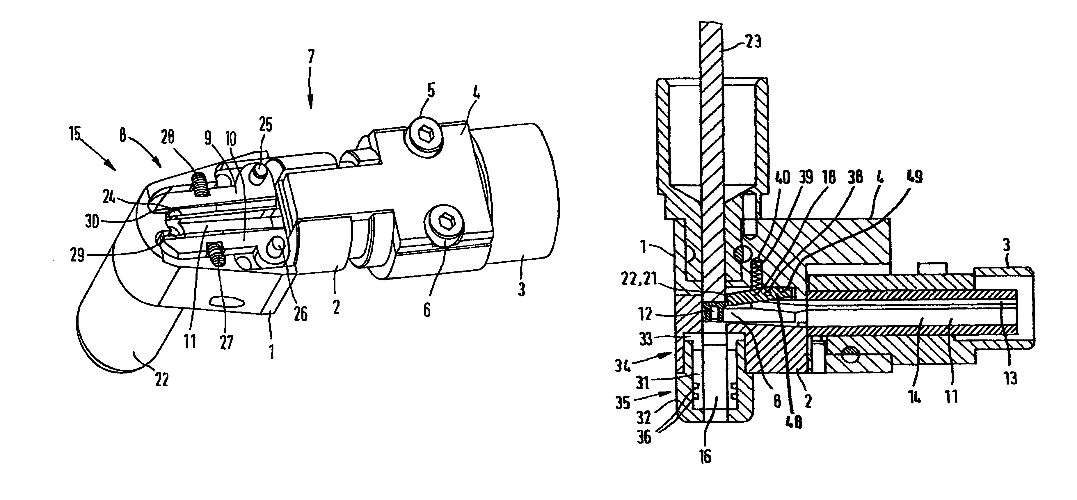
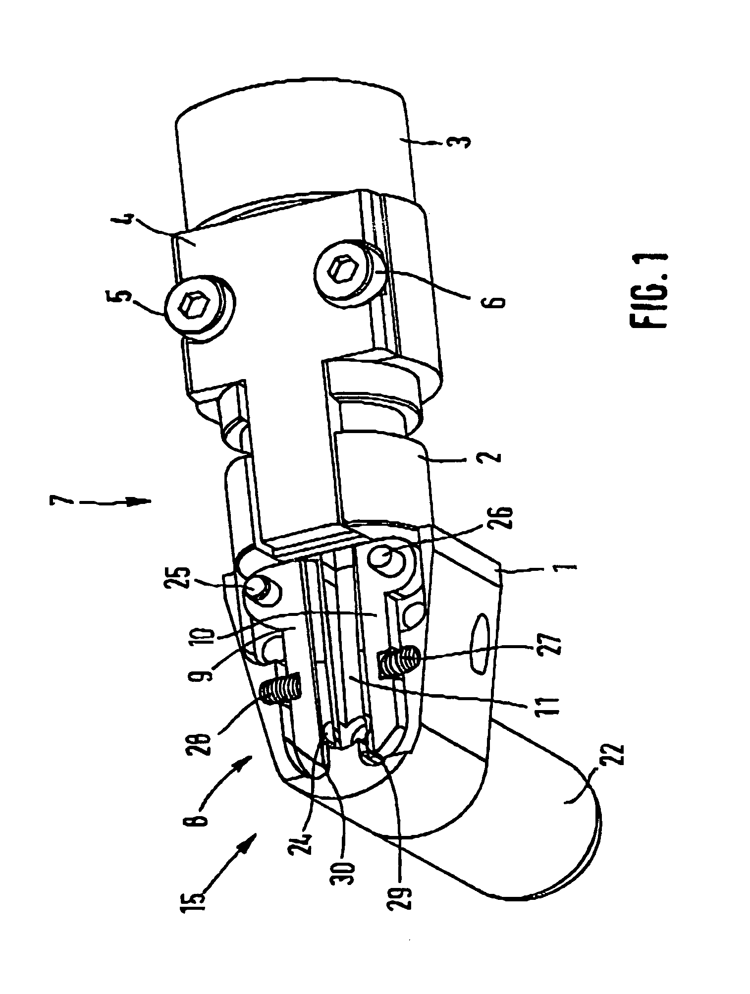
[0033]FIG. 1 shows, in part, a conveyor for elongate components designed with a head and a shank. The conveyor comprises a casing 1. The casing 1 comprises a connecting piece 2 by means of which the casing 1 can be connected to a feed conduit 3. For fixing the feed conduit 3 on the casing 1 there is provided a connecting member 4 which is connected to the casing 1 or the connecting piece 2 by screws 5 and 6.

[0034]The conveyor comprises a feed arrangement 7 having a transfer arrangement 8. The transfer arrangement 8 comprised two positioning segments 9, 10. The positioning segments 9, 10 partially limit a feed duct 11 which is continued in the connecting piece 2 and the feed conduit 3.

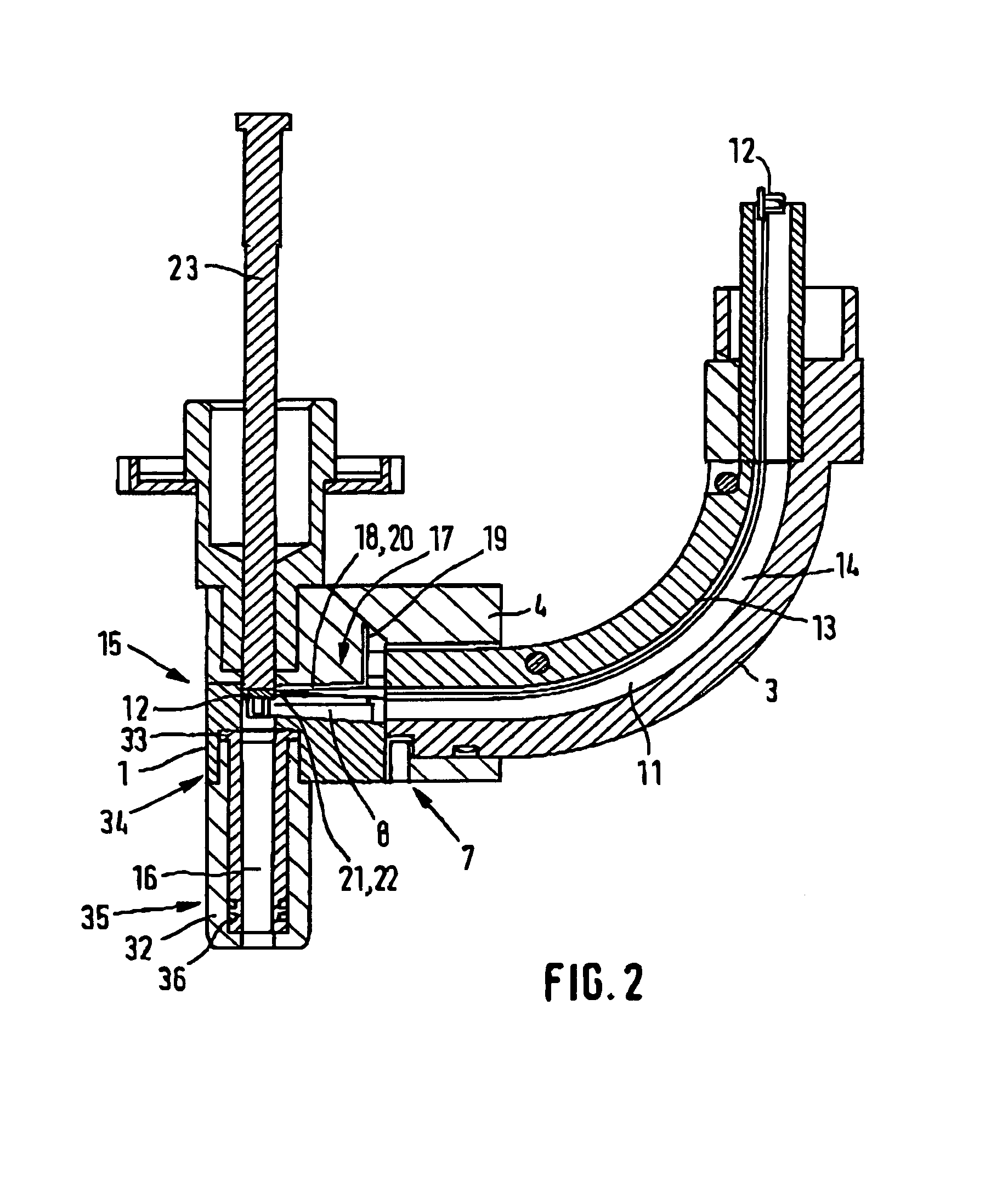
[0035]The remainder of a conveyor is described with reference to the embodiment illustrated in FIG. 2.

[0036]The conveyor is proposed for elongate components 12 designed with a head and a shank. The components 12 can be fed to the conveyor via a feed conduit 3. The feed conduit 3 comprises a feed duct 11...


PUM

PropertyMeasurementUnit
distanceaaaaaaaaaa
resilientaaaaaaaaaa
force of gravityaaaaaaaaaa

Abstract

The invention relates to a conveyor for elongate components (12) designed with a head and a shank. The conveyor comprises a feed arrangement (7). The feed arrangement (7) comprises a transfer arrangement (8) with a transfer region (15) in which a component (12) can be positioned. In the transfer region (15), a feed duct (11) having a head guiding duct (13) and a shank guiding duct (14) passes into a conveying duct (16). The transfer arrangement (8) comprises at least one catch unit (17). The catch unit (17) comprises at least one catch element (18). The catch element (18) is arranged opposite the head guiding duct (13) and penetrates at least partially therein. It can be deflected from the head guiding duct (13) against a spring force.

Description

BACKGROUND OF THE INVENTION[0001]The invention relates to a conveyor for elongate components designed with a head and a shank, in particular rivets, screws, weld studs and the like, according to the preamble of claim 1.[0002]It is known to use conveyors for the automated supply of elongate components designed with a head and a shank. These conveyors are used, in-particular, for stud welding devices, punch riveting devices or the like.[0003]German Patent No. 2 403 904 discloses a conveyor for elongate components designed with a head and a shank. The conveyor comprises a feed duct which passes into a conveying duct. Inside the conveying duct is arranged a plunger by means of which the component can be conveyed within the conveying duct to a free end portion of the conveying duct. The plunger can be pulled back sufficiently far within the conveying duct that it clears the feed duct. According to German Patent No. 2 403 904, the conveying duct extends such that the components pass into ...

Claims


Application Information

Patent Timeline
Patent Type & Authority Patents(United States)
IPC IPC(8): B21J15/02B21J15/32B23P19/00B23Q7/10B24B5/35B24B41/00B25B31/00B25C1/00B65G51/02
CPCB21J15/025B21J15/32B23P19/006B24B41/002B24B5/355Y10T29/49956Y10T29/53774
Inventor MAUER, DIETEROPPER, REINHOLDMOSER, JOACHIM
Owner NEWFREY
Why Eureka
Try Eureka