Cap assembly and cap for automatic fastener driver

a technology of automatic fastener and cap, which is applied in the direction of packaging, nailing tools, other accessories, etc., can solve the problems of undesirable polymer tape, especially when applied to the tops of caps, and achieve the effect of reducing the number of caps

Inactive Publication Date: 2005-11-29
NAT NAIL
View PDF87 Cites 32 Cited by
  • Summary
  • Abstract
  • Description
  • Claims
  • Application Information

AI Technical Summary

Benefits of technology

[0011]In accordance with the present invention, a cap assembly for an automatic cap feeder and fastener driver comprises a plurality of relatively thin metal discs that can be pierced by the fastener of a fastener driver such as a nail gun without damaging the nail or the gun, with the caps being connected together by a paper backed adhesive tape mounted on the undersides of the concave caps, with the caps having outer edges that cause the tape to be severed from the strip of caps when the caps are driven into a substrate after a nail has penetrated the caps.
[0012]In the preferred practice of the present invention, the caps are formed of a thin cold rolled steel having relatively sharp cutting peripheral edges with any burred edge facing up. Preferably, two sided galvanized steel is employed. The caps conventionally are approximately one inch in diameter and preferably are no greater than about 0.018 inches thick, desirably between 0.012 and 0.016 inches thick, and more preferably about 0.013 inches thick. The caps may have holes but do not require holes because the fasteners can be driven through the surface of the caps without a hole. Other metals such as aluminum or other steel can work as long as they can be pierced with the selected nail without bending the nail. The caps have a domed concave shape that enhances the peripheral gripping capabilities of the caps.
[0013]The preferred tape of the present invention is a paper backed tape coated on one side with a pressure sensitive rubber adhesive. Any substantial equivalent is satisfactory. This tape is similar in characteristics to masking tape. The preferred tape desirably is about ⅜ inch wide and has a backing material 2 mils thick and an adhesive coating 3 mils thick. The tape dimensions can be varied, as long as the tensile strength of the tape is sufficient to permit the caps to be fed without tape breakage. Also the width of the tape is less than the width of the caps and the tape is positioned inside the edges of the caps, so that the caps will completely sever the tape when they are dispensed by a fastener driver.
[0014]An important feature of the tape is that it can be severed more easily under an impact load than a polyester tape (which tends to stretch more readily), and it is not necessary to first pierce the tape in order to create a weakened area where a stress tear will propagate. Polyester tape, particularly when applied to the tops of the caps, is undesirable because the sharp, upwardly facing burred edge on the metal caps tends to cut the tape.
[0015]With the caps of the present invention, the caps can be substituted easily for plastic caps in applicant's automatic cap feeder and the caps themselves will sever the tape connecting the caps to the other caps as they are driven. The tape is then positioned under each cap and does not remain stuck to the outer surface of the cap, where it may be undesirable for aesthetic or functional purposes. Cap spacing is not too important with the use of paper backed tape positioned under the caps. A spacing of 0.050 of an inch is satisfactory.

Problems solved by technology

Polyester tape, particularly when applied to the tops of the caps, is undesirable because the sharp, upwardly facing burred edge on the metal caps tends to cut the tape.

Method used


Image

  • Cap assembly and cap for automatic fastener driver
  • Cap assembly and cap for automatic fastener driver
  • Cap assembly and cap for automatic fastener driver

Examples


Embodiment Construction

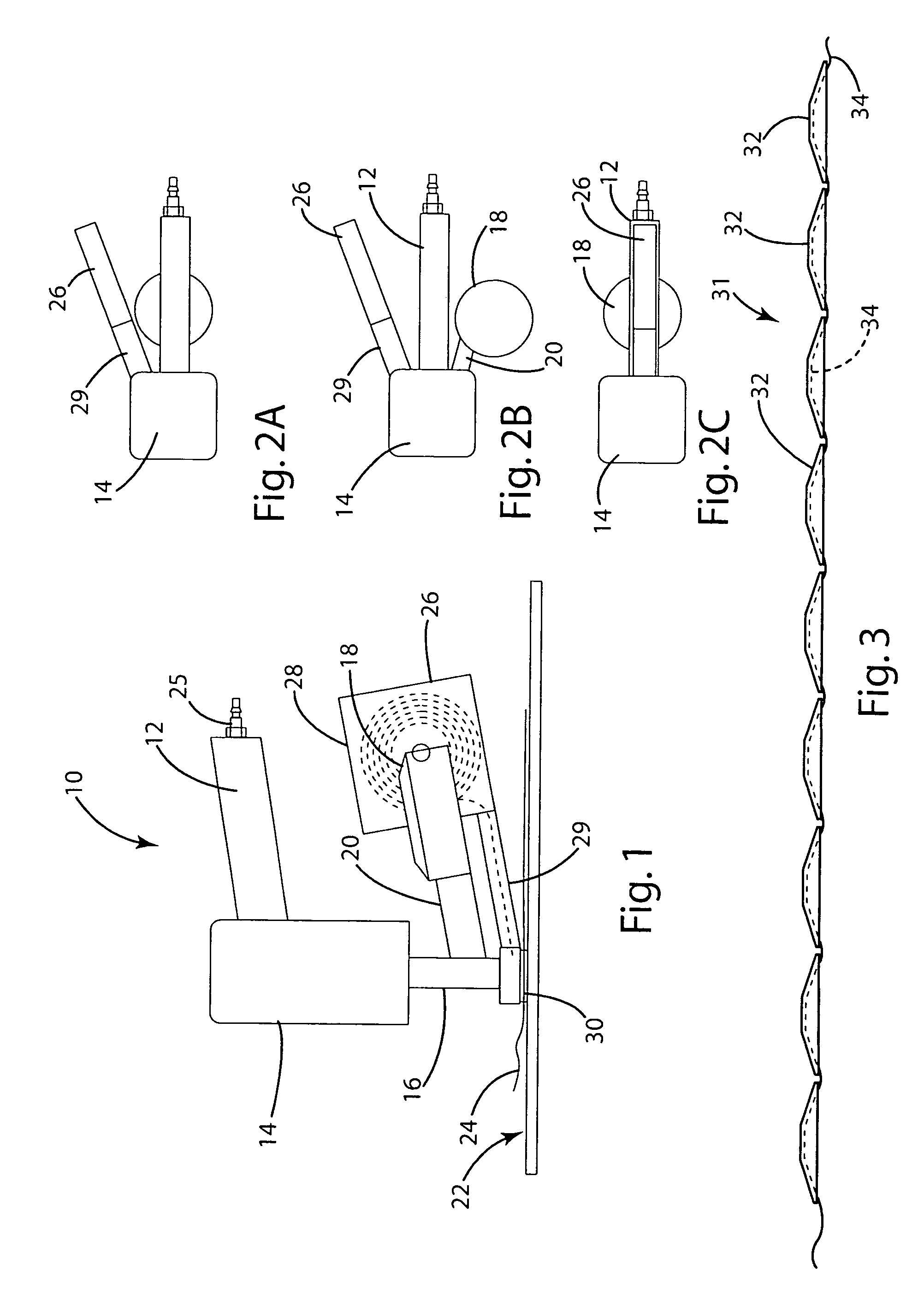
[0040]Referring now to the drawings, a conventional nail gun 10 shown schematically in FIG. 1 comprises a handle 12, a body or a housing 14 that houses a pneumatic drive cylinder, and a nail driver 16, which reciprocates vertically to drive nails. Nails are stored in a nail magazine or basket 18 adjacent driver 16 and are fed through a passage or track 20 into axial alignment with driver 16. When a nail is positioned in driving position and a trigger on the gun is actuated (and a safety is retracted) driver 16 reciprocates and drives a nail into a substrate 22, which may be covered by foam board insulation or roofing felt 24 or the like. Pressurized air is supplied to the gun through fitting 25.

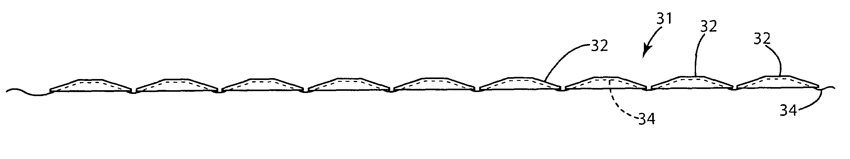
[0041]In applicant's cap feeder, as described in the above referenced patent application, a cap magazine or basket 26 positioned adjacent the nail basket 18 houses a plurality of caps 32 on a spool or reel 28. The caps are connected edge to edge and fed in a line along a cap slide track 29 to...


PUM


Abstract

A cap assembly for an automatic cap feeder and fastener driver comprises a plurality of relatively thin, domed metal discs that can be pierced by fasteners discharged from a fastener driver such as a nail gun without bending the nail or jamming the driver, with the caps being connected together by a paper backed adhesive tape mounted on the undersides of the concave caps, with the caps having outer edges that are sufficiently sharp that they sever the tape from the strip of caps when the caps are driven into a substrate after a fastener has penetrated the caps. The fastener driver includes improved feeder teeth and an anti-backup pawl that extend into recesses in the track. A cover encloses an open edge of a cap storage basket.

Description

CROSS-REFERENCES TO RELATED APPLICATIONS[0001]“This is a division of application Ser. No. 09 / 789,305, filed Feb. 20, 2001, (now U.S. Pat. No. 6,779,700),” claiming the benefit of U.S. Provisional Patent Application Ser. No. 60 / 183,402, filed on Feb. 18, 2000.STATEMENT REGARDING FEDERALLY SPONSORED RESEARCH OR DEVELOPMENT[0002]Not Applicable.BACKGROUND OF THE INVENTION[0003]Automatic fastener drivers such as nail guns are well known. In a typical nail gun a pneumatic or otherwise powered driver actuated by a trigger mechanism drives nails from a coil of collated nails into a substrate.[0004]When a sheet material or a layer of foam insulation is to be attached to the substrate, it is a common practice to employ a washer or cap with the nail or fastener. The washer or cap (which will be called a cap herein) has a larger diameter than the head of the fastener and is typically formed of a resilient material in a domed or concave shape, with the concave side of the cap facing toward the s...

Claims


Application Information

Patent Timeline
Patent Type & Authority Patents(United States)
IPC IPC(8): B25C1/00B25C5/16
CPCB25C1/006B25C5/1693Y10S206/82
Inventor BRUINS, ROGER C.VANDEN BERG, ROGER A.
Owner NAT NAIL
Why Eureka
Try Eureka