Multi-mode/multi-band power amplifier

a power amplifier and multi-mode technology, applied in the field of wireless communication, can solve the problems of increasing the power consumption of the device, reducing the battery life, and countering the current approach used to implement multi-mode amplifiers capable of operating at multiple frequencies

Inactive Publication Date: 2005-11-29
QORVO US INC
View PDF30 Cites 91 Cited by
  • Summary
  • Abstract
  • Description
  • Claims
  • Application Information

AI Technical Summary

Benefits of technology

[0006]In one embodiment, each of the multiple matching circuits includes multiple capacitive circuits coupling the signals in the different frequency bands to each transistor in an output stage of the wideband power amplifier. Each of the multiple matching circuits further includes at least one inductive shunt

Problems solved by technology

Unfortunately, these design goals are counter to current approaches used to implement multi-mode amplifiers capable of operating at multiple frequencies, because multi-mode amplifiers are required to operate

Method used


Image

  • Multi-mode/multi-band power amplifier
  • Multi-mode/multi-band power amplifier
  • Multi-mode/multi-band power amplifier

Examples


Embodiment Construction

[0015]The embodiments set forth below represent the necessary information to enable those skilled in the art to practice the invention and illustrate the best mode of practicing the invention. Upon reading the following description in light of the accompanying drawing figures, those skilled in the art will understand the concepts of the invention and will recognize applications of these concepts not particularly addressed herein. It should be understood that these concepts and applications fall within the scope of the disclosure and the accompanying claims.

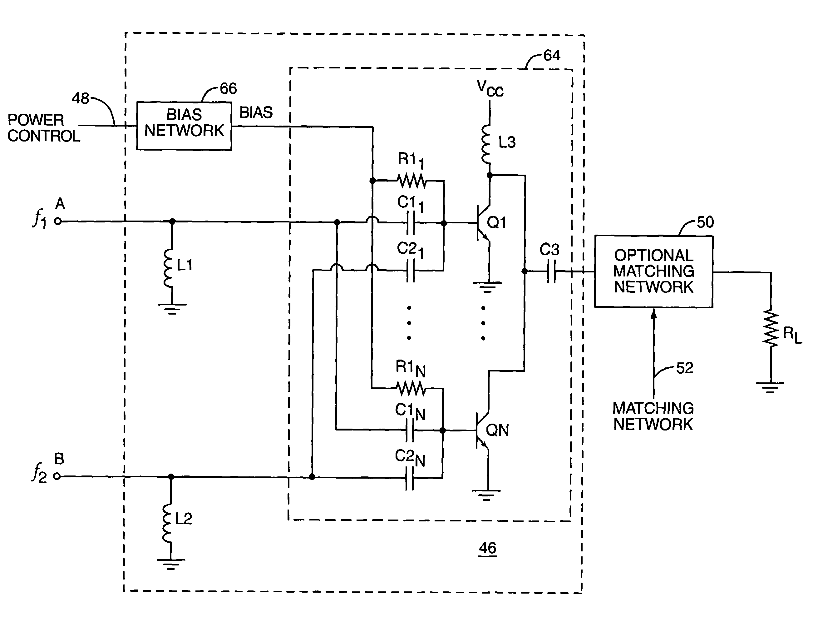
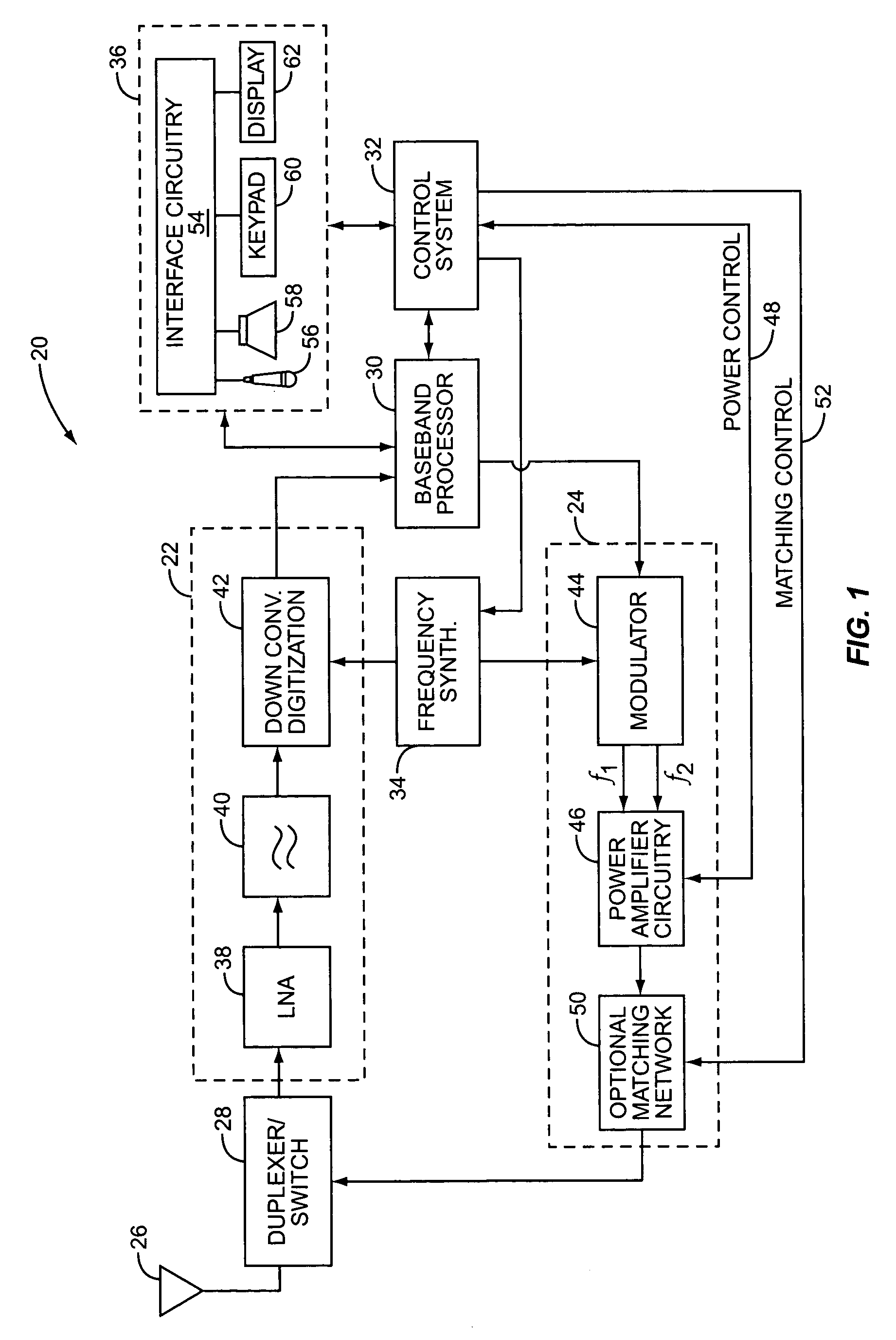
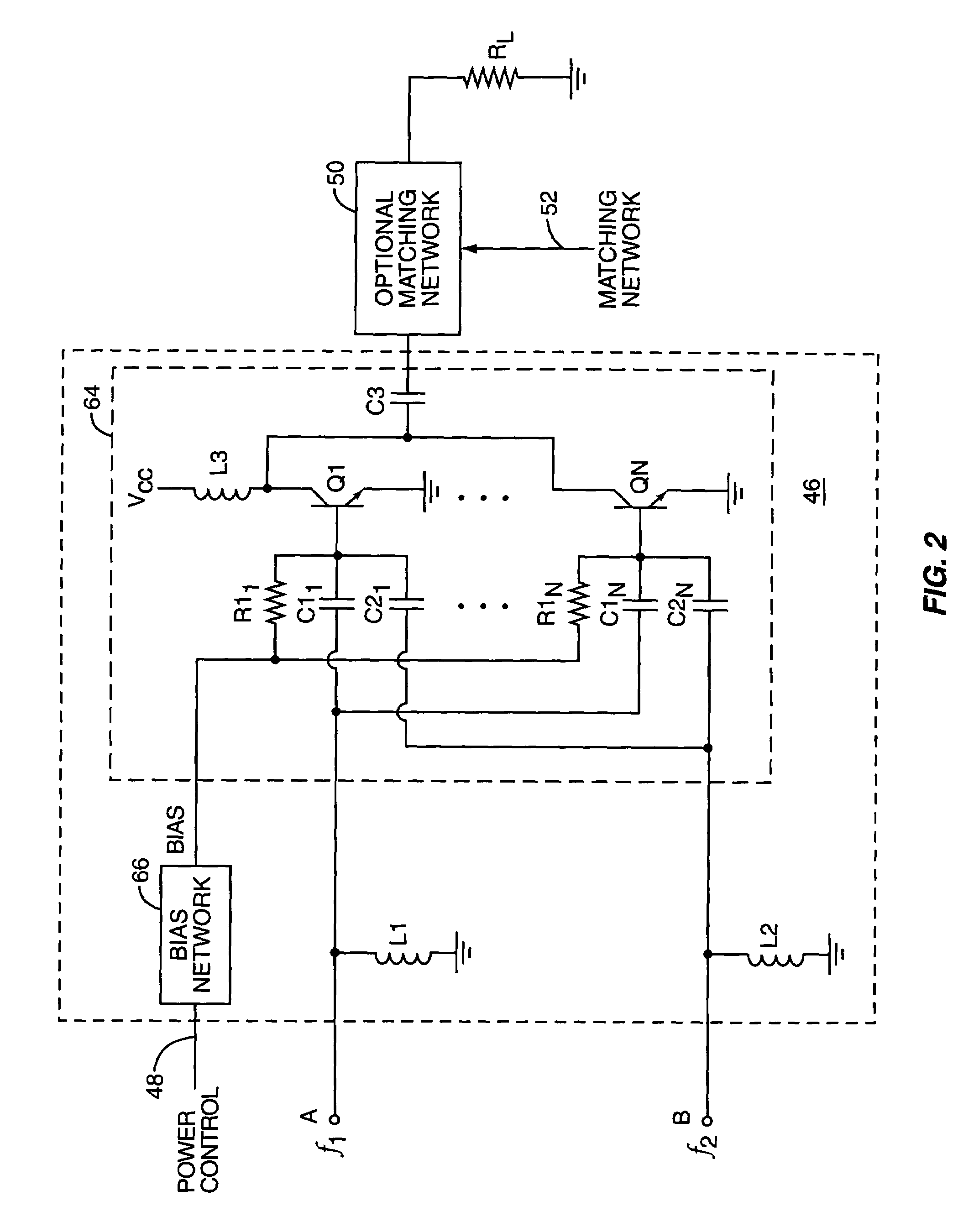
[0016]The present invention may be incorporated in a mobile terminal 20, such as a mobile telephone, wireless personal digital assistant, or like communication device. The basic architecture of a mobile terminal 20 is represented in FIG. 1 and may include a receiver front end 22, a radio frequency transmitter section 24, an antenna 26, a duplexer or switch 28, a baseband processor 30, a control system 32, a frequency synthesizer 3...


PUM


Abstract

The present invention provides a wideband power amplifier for a multi-mode or multi-band wireless communication device. The wideband power amplifier is configured to amplify signals in different frequency bands corresponding to different operating modes. In general, the wideband power amplifier includes multiple matching circuits that operate to combine the signals in the different frequency bands and provide a combined signal to each transistor in an output stage of the wideband power amplifier.

Description

FIELD OF THE INVENTION[0001]The present invention relates to a power amplifier for wireless communications, and more particularly relates to a power amplifier for use in multi-mode wireless communication devices.BACKGROUND OF THE INVENTION[0002]The present invention is particularly useful in mobile terminals, such as personal communication assistants, pagers, headsets, wireless modems, analog and digital cellular telephones, and the like. Since many of these devices are battery-powered, amplifier efficiency is preferably maximized to extend battery life. When amplifiers are designed for their highest efficiency in converting DC energy into RF energy, parasitic losses are minimized, bandwidths are reduced to a bare minimum, harmonics are terminated, and high-Q matching networks are employed. Unfortunately, these design goals are counter to current approaches used to implement multi-mode amplifiers capable of operating at multiple frequencies, because multi-mode amplifiers are require...

Claims


Application Information

Patent Timeline
IPC IPC(8): H03F1/02H03F3/189H03F3/191H03F3/60H03F3/68
CPCH03F1/0277H03F3/189H03F3/602H03F3/68H03F2200/111H03F2200/372
Inventor DENING, DAVID
Owner QORVO US INC
Why Eureka
Try Eureka