Edge card connector assembly with keying means for ensuring proper connection

Active Publication Date: 2006-01-12
MOLEX INC
View PDF28 Cites 63 Cited by
  • Summary
  • Abstract
  • Description
  • Claims
  • Application Information

AI Technical Summary

Benefits of technology

[0006] Accordingly, it is a general object of the present invention to provide a low profile connector in which the terminals may have varying shapes for contro

Problems solved by technology

However, low profile connectors, such as those used in SFP (Small Form Factor Pluggable) and SFP-like applications are desired in electronic devices in which space is a premium and thus it is difficult to control the impedance by modifying the spacing and size of the terminals in a reduced-size connector housing.
When the terminals are modified, it becom

Method used


Image

  • Edge card connector assembly with keying means for ensuring proper connection
  • Edge card connector assembly with keying means for ensuring proper connection
  • Edge card connector assembly with keying means for ensuring proper connection

Examples


Embodiment Construction

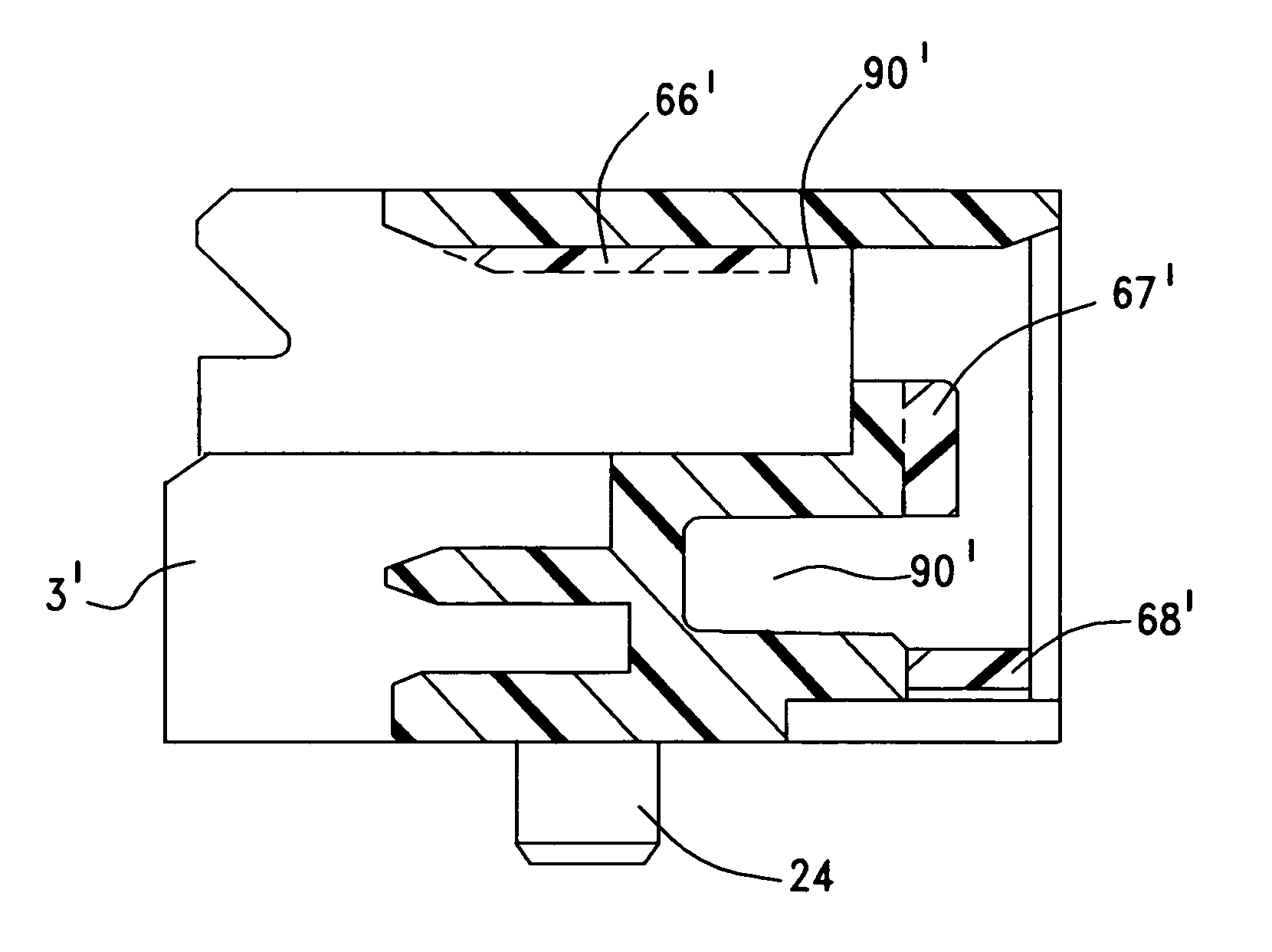
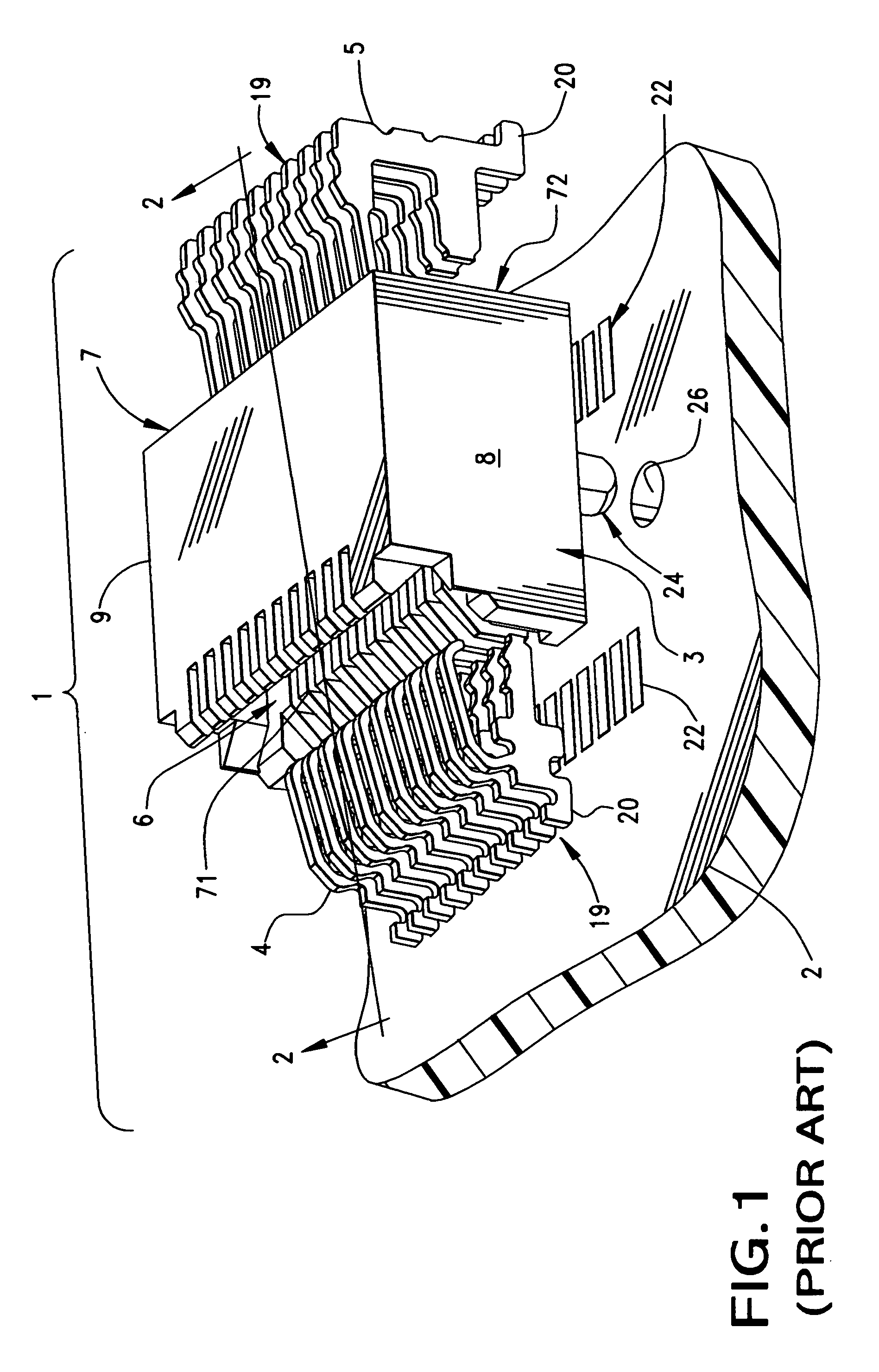
[0044]FIG. 1 illustrates a known connector assembly, generally designated as 1, that will be used to explain the environment in which the present invention operates. The connector assembly 1 is a surface-mount style and is intended for mounting to a printed circuit board 2. The connector assembly includes an insulative housing 3, preferably formed from a dielectric material, and a plurality of conductive terminals 19 are supported in the housing 3. The terminals 19 are arranged in two distinct sets of first terminals 4 and second terminals 5. This connector represents a connector structure that is commonly used in Small Form Pluggable-module applications.

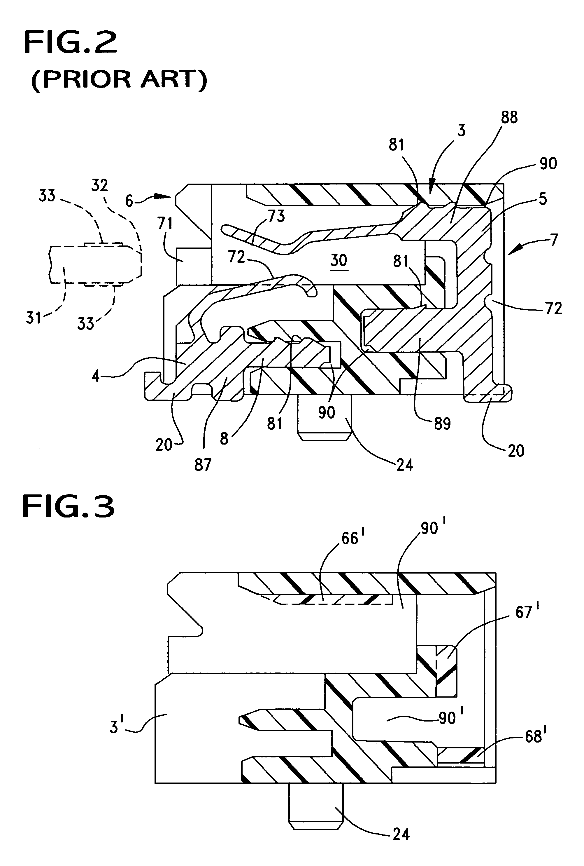
[0045] The connector housing has a configuration which includes a plurality of distinct faces and these faces include a first, or front face 6 and an opposing second, or rear face, 7. Side faces or sidewalls 8, 9 are seen to interconnect the front and rear faces 6, 7 of the housing together, and in the embodiment illustrated, the h...


PUM


Abstract

A surface mount connector for high speed data transfer application has an insulative housing with a circuit card-receiving slot disposed along a front face thereof. A plurality of conductive terminals are supported by the housing so that contact portions of the terminals extend into the card slot. The terminals are supported on opposite faces of the connector housing, specifically the top and bottom faces thereof, and each of the terminals includes a tail portion, a contact portion and a retention portion that engages the connector housing so that the contact portions are cantilevered in their extent within the housing. The housing includes a hollow recess formed on its bottom that opens to the front of the connector housing. This recess serves as a keyway that may receive a male portion of an opposing mating connector to ensure the mating connector is oriented properly before engagement.

Description

REFERENCE TO RELATED APPLICATIONS [0001] This application claims priority from U.S. Provisional Patent Application No. 60 / 586,488, filed Jul. 7, 2004. BACKGROUND OF THE INVENTION [0002] The present invention is directed generally to edge card connectors and, more specifically to edge card connectors in which the connector impedance may be controlled by shaping of the connector terminals and in which the connector includes a means for ensuring proper connection with an opposing, mating connector. [0003] High speed data transfer systems require electrical connectors in which the electrical impedance can be controlled in order to maintain the required data transfer rate of the electrical system. It is desirable at high speed data transfer rates to obtain a specific impedance in a connector that matches the impedance of the entire electronic system, i.e., the circuits on a circuit board of an electronic device and either the circuits of opposing electronic device or in a transmission ca...

Claims


Application Information

Patent Timeline
IPC IPC(8): H01R24/00H01R12/71
CPCH01R12/57H01R13/64H01R12/725H01R12/721H01R23/7073
Inventor REGNIER, KENT E.NEER, JAY H.
Owner MOLEX INC
Why Eureka
Try Eureka