Lighting device and vehicle headlamp

a technology for lighting devices and headlamps, which is applied in the direction of fixed installation, lighting and heating equipment, transportation and packaging, etc., can solve the problems of excessive current flowing to the lit light source, led breaking, and forward current increasing continuously, and achieves the effect of constant operating characteristics

Active Publication Date: 2013-12-05
PANASONIC INTELLECTUAL PROPERTY MANAGEMENT CO LTD
View PDF3 Cites 28 Cited by
  • Summary
  • Abstract
  • Description
  • Claims
  • Application Information

AI Technical Summary

Benefits of technology

[0025]According to the present invention, the control unit of the switching circuit controls the impedance of the active element such that the current flowing through the active element or the end-to-end voltage of the active element matches the target value set by the switching control circuit. Therefore, a constant operating characteristic can be obtained during a switch in the ON / OFF condition of the active element, and a delay in the start of a switch in the ON / OFF condition of the active element can be suppressed.

Problems solved by technology

An LED is lit by applying a voltage exceeding a forward voltage (a barrier voltage) thereto, but since an LED has a similar load characteristic to a constant voltage load, a forward current may increase continuously when a source impedance is low, and as a result, the LED may break.
However, a time delay occurs in the power supply circuit from a point at which the active element is switched ON to a point at which an output voltage decreases due to an effect of a capacitor provided at an output stage, for example, and as a result, an excessive current may flow to the lit light source immediately after the active element is switched ON.
This excessive current may cause a solid state light source such as an LED to deteriorate or malfunction.
Further, rapid load variation may cause the power supply circuit to generate unstable output such as ringing.
It is therefore difficult to obtain a constant operating characteristic when switching the active element ON and OFF with a configuration such as those described in Documents 2 and 3, wherein the control signal of the active element is simply slowed down.

Method used


Image

  • Lighting device and vehicle headlamp
  • Lighting device and vehicle headlamp
  • Lighting device and vehicle headlamp

Examples


first embodiment

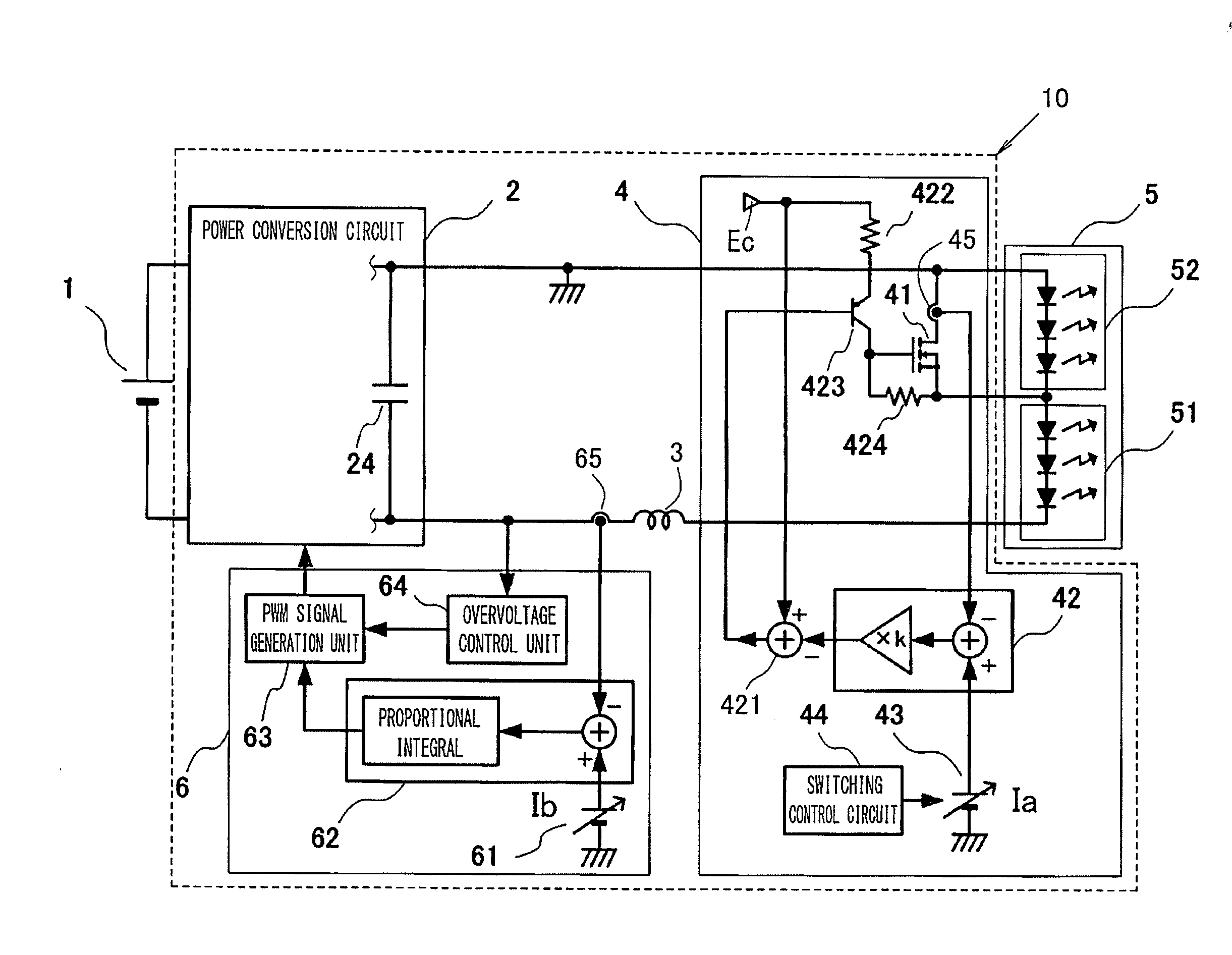
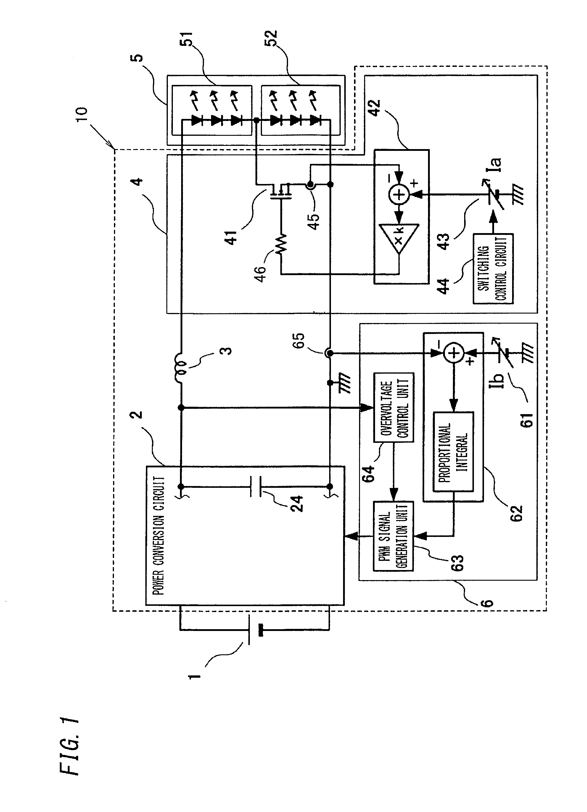
[0050]As shown in FIG. 1, a lighting device 10 according to this embodiment includes a power conversion circuit 2 that supplies power to a light source group 5 using an output of a direct current power supply 1 as an input, an output control circuit 6 that controls the power conversion circuit 2, and a switching circuit 4 to be described below. Note that the direct current power supply 1 may be a battery or the like, or a power supply circuit that rectifies and smoothens an output voltage of an alternating current power supply such as a commercial power supply in order to convert the output voltage into a direct current voltage.

[0051]The light source group 5 is constituted by a first light source block 51 and a second light source block 52, in each of which a plurality of light emitting diodes (LEDs) serving as solid state light sources are connected in series. In the example of FIG. 1, three LEDs are connected in series in each of the first light source block 51 and the second ligh...

second embodiment

[0101]As shown in FIG. 6, the lighting device 10 according to this embodiment differs from the lighting device 10 according to the first embodiment in that the current detection circuit for detecting the current flowing to the active element 41 doubles as a detection unit 65 for controlling the output of the power conversion circuit 2. Hereafter, common reference symbols have been allocated to similar configurations to the first embodiment, and where appropriate, description thereof has been omitted.

[0102]Note that in the example of FIG. 6, the power conversion circuit 2 is constituted by a flyback converter. The power conversion circuit 2 is configured such that a series circuit of a primary winding of a flyback transformer 21 and a switching element 22 are connected between output ends of the direct current power supply 1, while a diode 23 and the capacitor 24 are connected in series between respective ends of a secondary winding of the flyback transformer 21. The detection unit 6...

third embodiment

[0106]As shown in FIG. 7, the lighting device 10 according to this embodiment differs from the lighting device 10 according to the first embodiment in that the current flowing to the active element 41 is controlled to the target value Ia using a current mirror circuit in place of the error amplifier 42 and the current detection circuit 45. Hereafter, common reference symbols have been allocated to similar configurations to the first embodiment, and where appropriate, description thereof has been omitted.

[0107]In the example of FIG. 7, the second light source block 52 is connected to the high potential side output of the power conversion circuit 2, and the first light source block 51 is connected to the low potential side output (the circuit ground). In the configuration shown in FIG. 7, the active element 41 is constituted by a PNP type transistor, and forms the current mirror circuit together with another PNP type transistor 425 and resistors 411, 424.

[0108]More specifically, a ser...


PUM


Abstract

A switching circuit includes an active element connected in parallel to a second light source block and having an impedance that varies in accordance with a control signal input into a control terminal, and switches the second light source block between a lit condition and an extinguished condition by switching the active element ON and OFF. The switching circuit adjusts the impedance of the active element so that a current flowing to the active element matches a target value set by a switching control circuit. When the active element is to be switched ON, the switching control circuit varies the target value gradually over time, and therefore an excessive load current can be prevented from flowing while the active element shifts from an OFF condition to an ON condition.

Description

BACKGROUND OF THE INVENTION[0001]1. Field of the Invention[0002]The present invention relates to a lighting device and a vehicle headlamp in which the number of light sources to be lit, from among a plurality of light sources connected in series, can be switched.[0003]2. Description of the Related Art[0004]In recent years, solid state light sources such as light emitting diodes (LEDs) have increased rapidly in popularity such that, for example, LEDs may even be used as vehicle headlamps in place of incandescent lamps such as halogen lamps. An LED is lit by applying a voltage exceeding a forward voltage (a barrier voltage) thereto, but since an LED has a similar load characteristic to a constant voltage load, a forward current may increase continuously when a source impedance is low, and as a result, the LED may break. As a simple solution to this problem, current limitation is performed using a current limiting resistor connected in series to the LED, but in a device requiring a com...

Claims


Application Information

Patent Timeline
Patent Type & Authority Applications(United States)
IPC IPC(8): H05B33/08F21S8/10H05B44/00
CPCH05B33/0815F21S48/1747F21S41/663H05B45/48H05B45/3725H05B45/385H05B47/24H05B45/37H05B45/54
Inventor NAKAMURA, TOSHIAKI
Owner PANASONIC INTELLECTUAL PROPERTY MANAGEMENT CO LTD
Why Eureka
Try Eureka