Theft detection system and method

Inactive Publication Date: 2005-11-29
CAVEO INVESTMENTS
View PDF14 Cites 107 Cited by
  • Summary
  • Abstract
  • Description
  • Claims
  • Application Information

AI Technical Summary

Benefits of technology

[0007]It is therefore an object of this invention

Problems solved by technology

However, because of their smaller size, computers are now easier to steal, for example, when left unattended for even a brief moment at an airport.
The primary problem with this device is that the computer is disabled whenever it is moved.
Therefore, if the owner of the computer enables the motion detector and then

Method used


Image

  • Theft detection system and method
  • Theft detection system and method
  • Theft detection system and method

Examples


Embodiment Construction

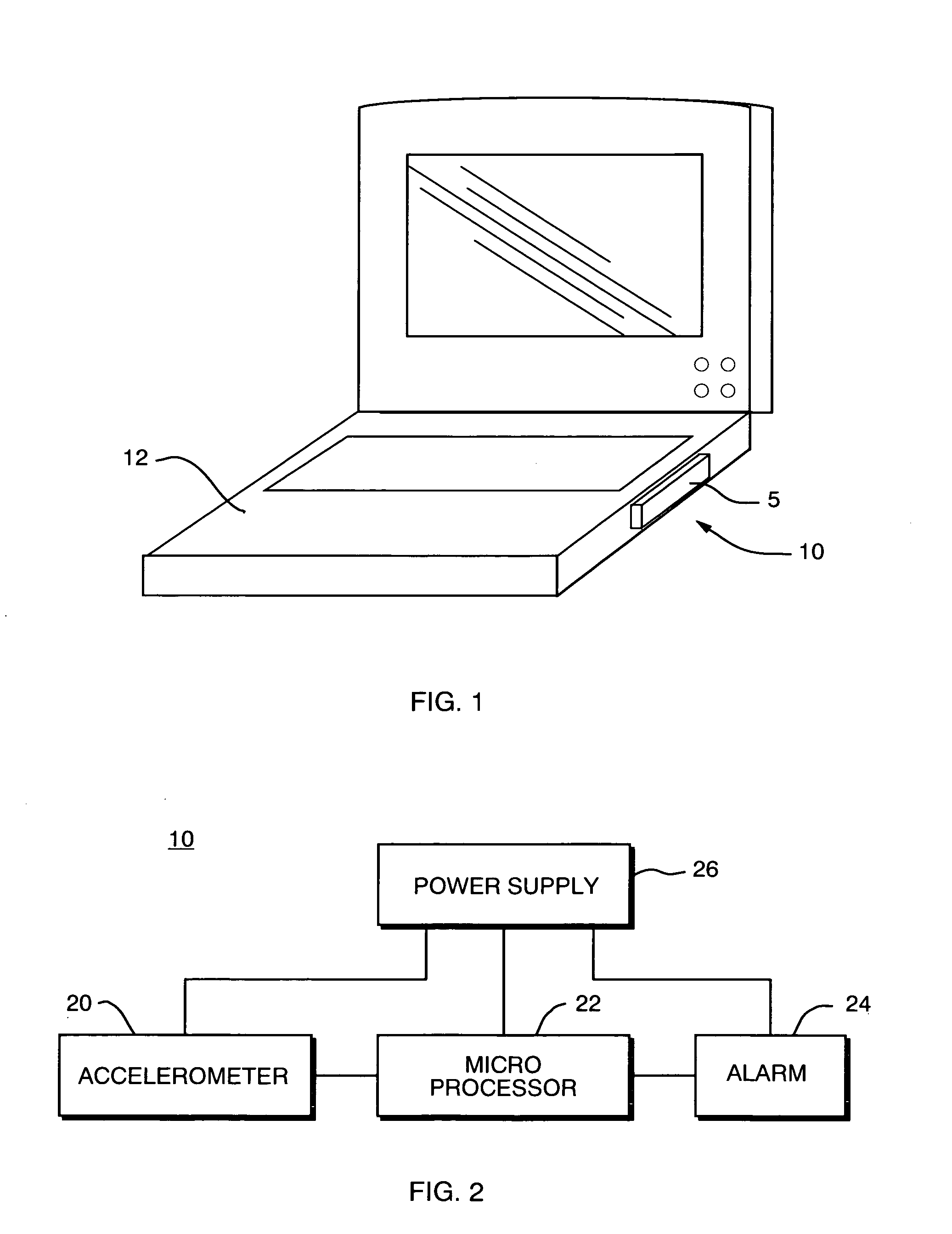
[0034]Theft detection system 10, FIG. 1, in one embodiment, is enclosed in a small housing 5 which can be secured to an object of value such as laptop computer 12. Other uses for system 10 includes personal data assistants, notebook computers, cellular telephones, other electronic devices, and even works of fine art. Alternatively, system 10 can reside on a PC card or even on an existing circuit board resident in an electronic device such as a computer.

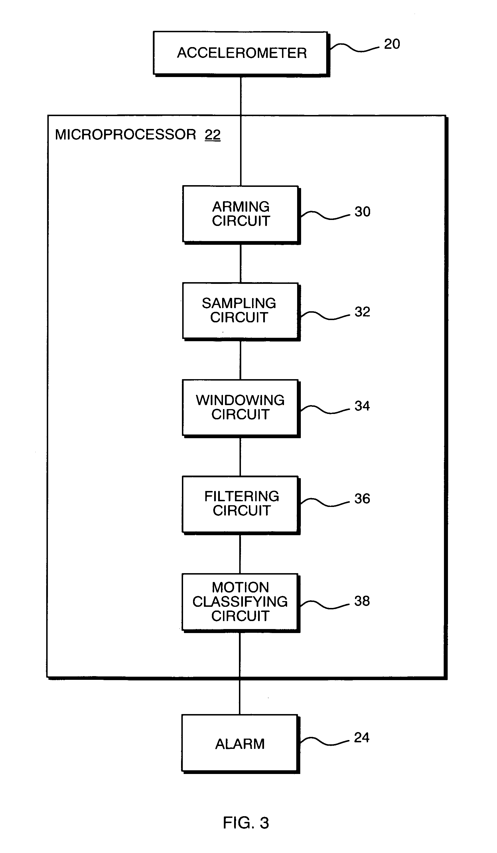
[0035]The primary components of the preferred theft detection system 10, in all embodiments, include a motion sensor such as accelerometer 20, FIG. 2, microprocessor 22, and alarm subsystem 24 (for example, an audible alarm). Power supply 26, for example, a lithium battery may be provided in some embodiments for providing power to accelerometer 20, microprocessor 22 and alarm 24. In an alternative embodiment, audible alarm 24 could be replaced or supplemented with an alarm mechanism which provides a signal to computer 12 to disable it...


PUM


Abstract

A theft detection system includes an accelerometer attachable to an object, the accelerometer providing an acceleration signal in response to movement of the object; an alarm mechanism for providing a signal in response to movement of the object; and for preventing false alarms, a filter programmed to determine the frequency of the acceleration signal and to provide an output to activate the alarm mechanism only when the frequency of the acceleration signal meets a predetermined criteria.

Description

RELATED APPLICATIONS[0001]This application claims priority of U.S. Provisional Application Nos. 60 / 164,709 filed Nov. 11, 1999; 60 / 157,766 filed Oct. 5, 1999; 60 / 134,575 filed May 17, 1999; and 60 / 154,818 filed Sep. 20, 1999.FIELD OF THE INVENTION[0002]This invention relates to a theft detection system which can be attached to valuable objects such as laptop computers, other electronic devices, and even works of fine art.BACKGROUND OF THE INVENTION[0003]Computers have conveniently become smaller and smaller in size. There are now notebook computers, hand held personal computers, and personal data assistants in addition to laptop computers.[0004]However, because of their smaller size, computers are now easier to steal, for example, when left unattended for even a brief moment at an airport.[0005]In U.S. Pat. No. 5,574,786, incorporated herein by this reference, a motion detector is coupled to a computer and the computer is disabled whenever it is moved.[0006]The primary problem with ...

Claims


Application Information

Patent Timeline
IPC IPC(8): G08B13/14G08B21/00
CPCG08B13/1436G08B29/185
Inventor LEE, W. DAVIDWELLS, MARTINVERPLAETSE, CHRISTOPHERTURNER, CHRISTOPHER
Owner CAVEO INVESTMENTS
Why Eureka
Try Eureka