Carrier mechanism

Inactive Publication Date: 2005-11-29
PIONEER CORP
View PDF3 Cites 1 Cited by
  • Summary
  • Abstract
  • Description
  • Claims
  • Application Information

AI Technical Summary

Benefits of technology

[0010]It is therefore an object of the invention to provide a carrier mechanism which is capable of positioning carrier means to a desired position with high accuracy.
[0011]To attain the object, the invention provides a carrier mechanism having accommodating means and carrier means, for carrying out positioning between the accommodating means and the carrier means, to thereby insert an object carried from the carrier means in to the accommodating means, or take the object accommodated in the accommodating means, out of the accommodating means to the carrier means, the carrier mechanism comprising driving means for moving the carrier means, and control means operable when the carrier means is moved to a desired position in one direction, for controlling the driving means so as to move the carrier means to a position in excess of the desired position and then to move the carrier means to the desired position, the control means controlling the driving means so as to move the carrier means to the desired position without exceeding the desired position when the carrier means is moved to the desired position in a direction opposite to the one direction.

Problems solved by technology

The actuator formed of the gears etc. is a movable mechanism, so that it unfavorably has a very small amount of plays, looseness, etc.
Therefore, although the motor 3 is electrically driven and controlled by the driving voltage V, which has been pulse-duration modulated, the actuator inevitably causes mechanical displacement in the movement of the carrier section 4, and therefore in some cases, the carrier section 4 cannot be positioned to the desired position.
That is, the apparatus of this kind is prone to undertake a slight amount of vertical displacement between the carrier section 4 and the desired position due to plays, looseness, etc.
Such displacement can make it impossible for the accommodated recording medium 1 from being smoothly taken out of the accommodating rack 2, or the carried recording medium 1 from being smoothly inserted into the accommodating rack 2, and can further cause a failure of the apparatus.

Method used


Image

  • Carrier mechanism
  • Carrier mechanism
  • Carrier mechanism

Examples


Embodiment Construction

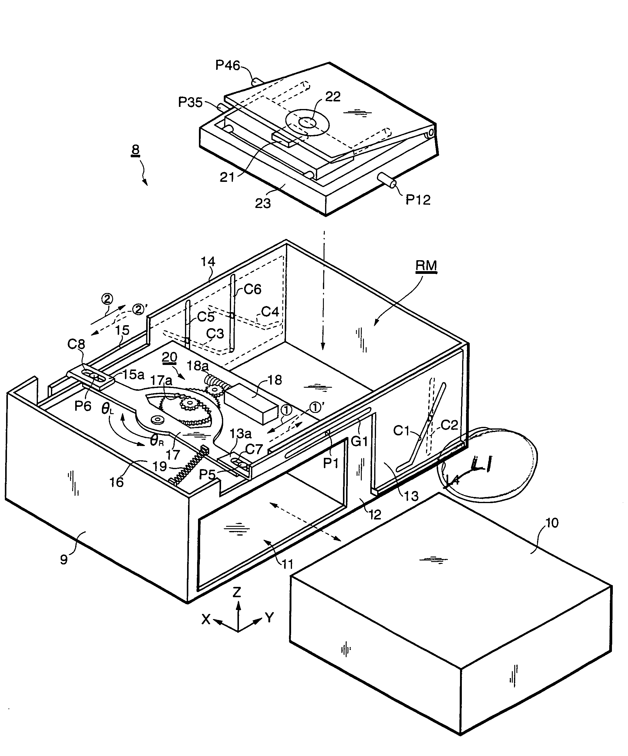
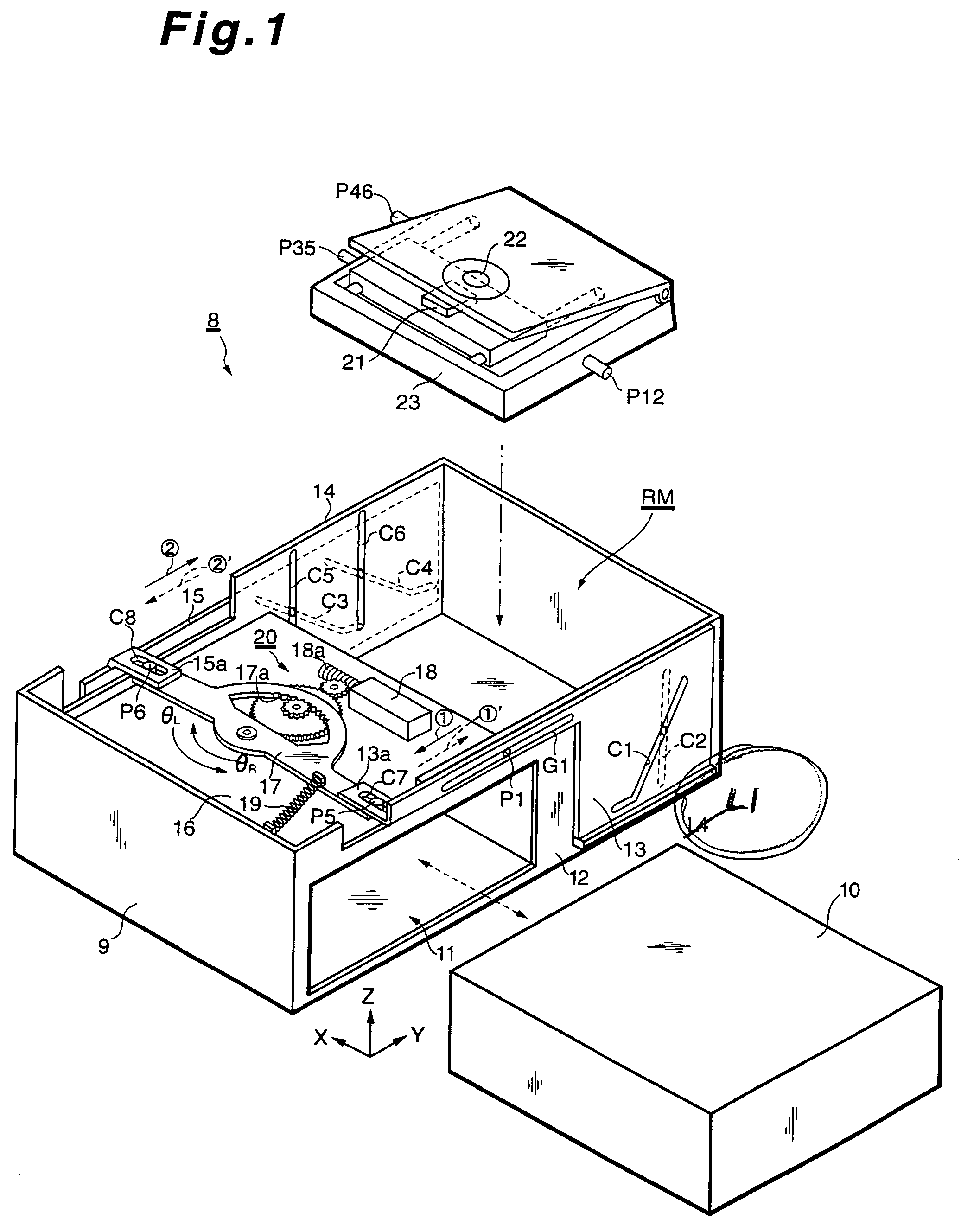
[0038]The invention will now be described in detail with reference to the drawings showing an embodiment thereof. In the following embodiment, description will be specifically made of a carrier mechanism for an information reproducing apparatus to be mounted in vehicles (hereinafter referred to as “the in-vehicle information reproducing apparatus), which plays back recording media, such as CD's (compact discs) or DVD's (digital versatile discs or digital video discs).

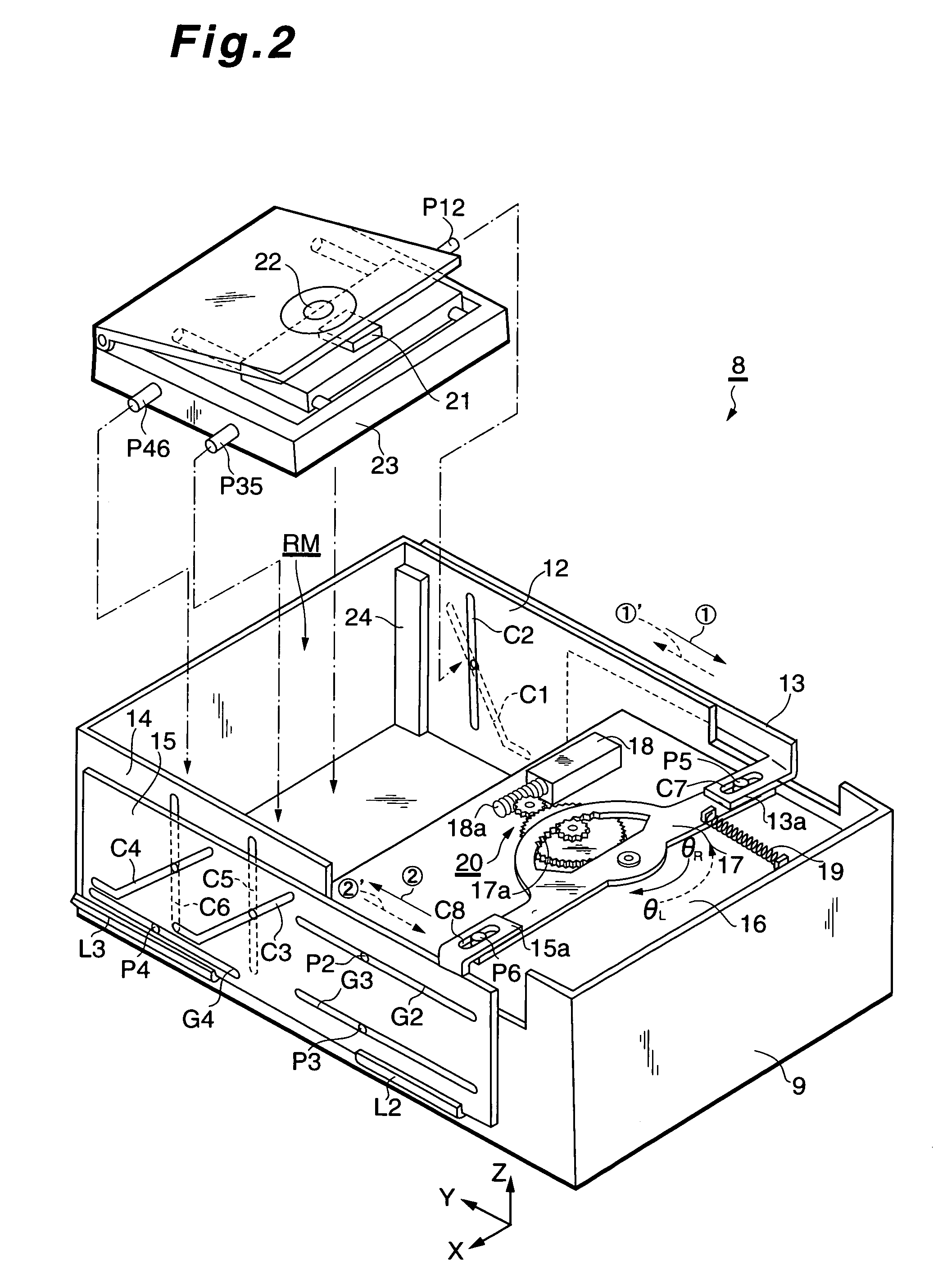
[0039]FIGS. 1 and 2 are perspective views each showing the construction of an essential part of an in-vehicle information reproducing apparatus in a disassembled state, in which FIG. 1 shows the information reproducing apparatus as viewed on the side of an operation panel thereof, while FIG. 2 shows the information reproducing apparatus as viewed on the side of a rear surface thereof. In the figures, rectangular coordinates X, Y, and Z represent horizontal directions and a height direction. Further, FIG. 3 is a perspect...


PUM


Abstract

There is provided a carrier mechanism which can move a carrier section 23 to a desired position with high accuracy. The carrier mechanism is comprised of the carrier section 23, a driving motor 18, and an actuator formed of a cam mechanism 13, 15 for transmitting a driving force of the driving motor 18 to the carrier section 23 to convey the same. When the carrier section 23 is moved upward with respect to the present position, the carrier section 23 is once moved (elevated) to a position in excess of a desired position, then moved downward from the exceeded position to the desired position. When the carrier section 23 is moved downward from the present position, the carrier section 23 is moved to the desired position without exceeding the desired position. By virtue of this operation, in both of the elevation and lowering of the carrier section 23, the carrier section 23 reaches the desired section by lowering thereto at its final stage of the movement. Further, the so-called actuator for driving the carrier section 23 is held in a predetermined direction, and therefore the carrier section 23 can be positioned to the desired position with high accuracy.

Description

BACKGROUND OF THE INVENTION[0001]This invention relates to a carrier mechanism, and more particularly to a carrier mechanism of this kind, which carries out positioning between accommodating means and carrier means, thereby inserting an object, such as a recording medium, which has been carried by the carrier means, into the accommodating means, or taking the accommodated object, such as the recording medium, out of the accommodating means to the carrier means.[0002]Conventionally, carrier mechanisms of this kind are known, for example, from Japanese Patent Laid-Open Publication Nos. Hei7-61523 and Hei10-91241. The conventional carrier mechanisms are for use in information reproducing apparatuses which each reproduces information recorded on a recording medium. FIG. 16A schematically shows the arrangement of one of the carrier mechanisms, for example, in which the carrier mechanism is formed of an accommodating rack 2 which can accommodate a plurality of recording media 1, a motor 3...

Claims


Application Information

Patent Timeline
IPC IPC(8): G11B17/22G11B7/00G11B17/26G11B17/30
CPCG11B17/30
Inventor SHIMAMURA, TAKAONAKAMURA, FUMIHIKOYOSHIMURA, HIDEAKIKAWAKITA, NOBUTAKA
Owner PIONEER CORP
Why Eureka
Try Eureka