Magnetic tucker bar for a printing press

a printing press and magnetic technology, applied in printing presses, office printing, printing, etc., can solve the problem of large number of pistons or air cylinders

Inactive Publication Date: 2005-12-06
GOSS INT AMERICAS
View PDF15 Cites 3 Cited by
  • Summary
  • Abstract
  • Description
  • Claims
  • Application Information

AI Technical Summary

Benefits of technology

[0013]By having a magnet on the tucker bar creating a repulsive force away from the tucker bar, the magnetic force can aid in the tucking motion, and moving parts can be reduced.

Problems solved by technology

A problem associated with present tucking devices is that a large number of pistons or air cylinders are needed across the width of the tucking device to properly tuck the tail of the plate into the slot of the plate cylinder.

Method used


Image

  • Magnetic tucker bar for a printing press
  • Magnetic tucker bar for a printing press
  • Magnetic tucker bar for a printing press

Examples


Embodiment Construction

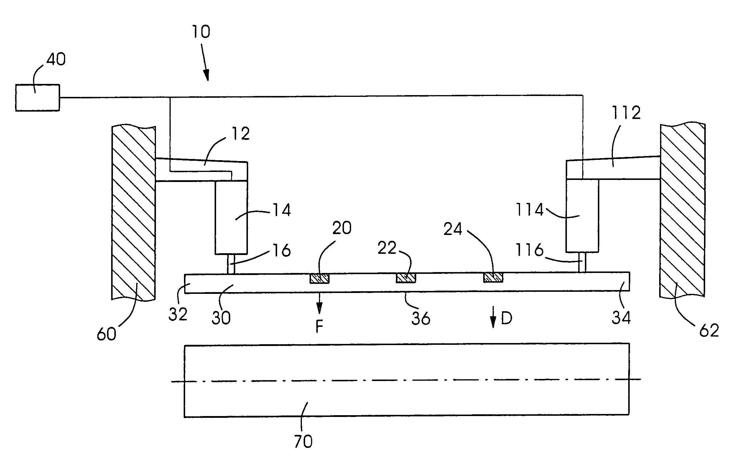
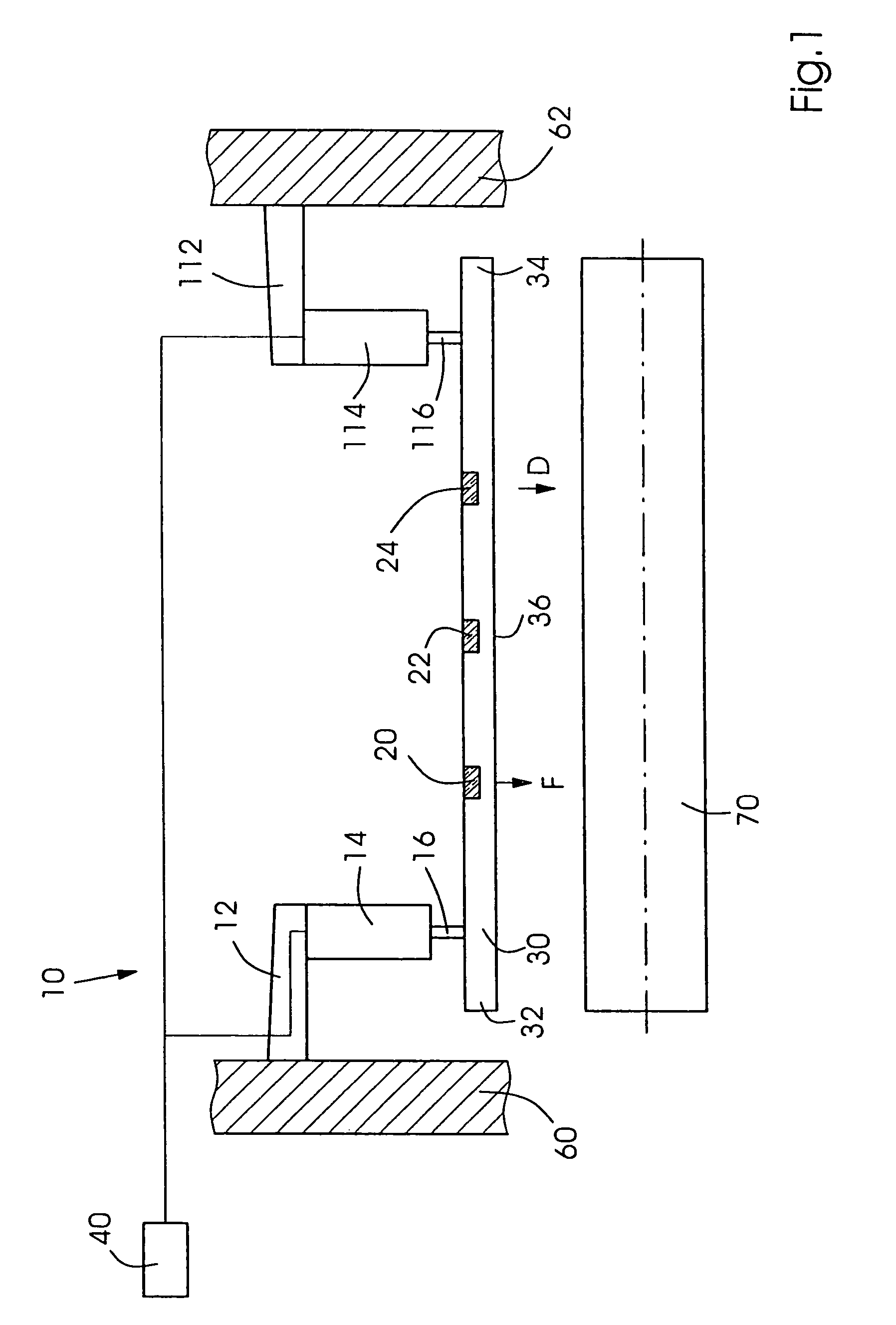
[0027]FIG. 1 shows a first embodiment of a tucking device 10 according to the present invention. Tucking device 10 includes a tucker bar 30 connected at one end 32 to a piston 16 of an air cylinder 14, and at the other end 34 to a piston 116 of an air cylinder 114. Air cylinder 14 is connected to a work side frame 60 of a printing press by a fixed bracket 12, and air cylinder 114 is connected to a gear side frame 62 of the printing press via a fixed bracket 112.

[0028]Air cylinders 14, 114 are driven in tandem by a controller 40, which can actuate bar 30 in direction D towards a plate cylinder 70. Plate cylinder 70 is rotatable with respect to frames 60, 62.

[0029]Magnets 20, 22, 24, which may be for example permanent or electrically-activated magnets, are located between the ends 32, 34 of the bar 30, and create a magnetic repulsive force F normal to the lower or tucking surface 36 of the tucker bar 30.

[0030]The magnetic force added to the force created by the air cylinders provides ...


PUM


Abstract

A tucking device for tucking a printing plate into a gap of a plate cylinder includes a tucker bar having a tucking surface and at least one magnet for creating a repulsive magnetic force at the tucking surface. An actuator connected to the tucker bar is used for moving the tucker bar to tuck the printing plate into the gap.

Description

CROSS-REFERENCE TO RELATED APPLICATIONS[0001]This application is a divisional of U.S. patent application Ser. No. 10 / 213,534, filed on Aug. 6, 2002, now U.S. Pat. No. 6,672,209 B1.BACKGROUND OF THE INVENTION[0002]The present invention relates generally to printing presses and more particularly to a tucker bar for tucking an edge of a plate into a plate cylinder of a printing press.[0003]U.S. Pat. No. 5,678,487 discloses an apparatus for mounting printing plates into an axially-extending gap in a plate cylinder. A tucking device has a plurality of tucking elements arranged along the width of the plate cylinder and its axially extending gap. Each of the tucking elements is driven by pistons, so that a plurality of pistons extend along the width of the tucking device. The '487 patent is hereby incorporated by reference herein.[0004]German Patent Application Nos. 100 01 324 and 100 01 328 disclose a device for pulling flexible printing plates onto a plate cylinder using a pressure rolle...

Claims


Application Information

Patent Timeline
Patent Type & Authority Patents(United States)
IPC IPC(8): B41F27/02B41F27/12
CPCB41F27/02B41F27/1206
Inventor CHARETTE, WILLIAM ALBERTLEMELIN, MICHAEL ROBERTZLATIN, LEV
Owner GOSS INT AMERICAS
Why Eureka
Try Eureka