
Internal combustion engine with modified shaft

a technology of internal combustion engine and shaft, which is applied in the direction of valve drive, machine/engine, oscillatory slide valve, etc., can solve the problems of inefficiency and restrictive linear airflow of valves, and achieve the effects of improving fuel economy, improving airflow and horsepower gain

Inactive Publication Date: 2011-09-01
MYERS RUSSELL S
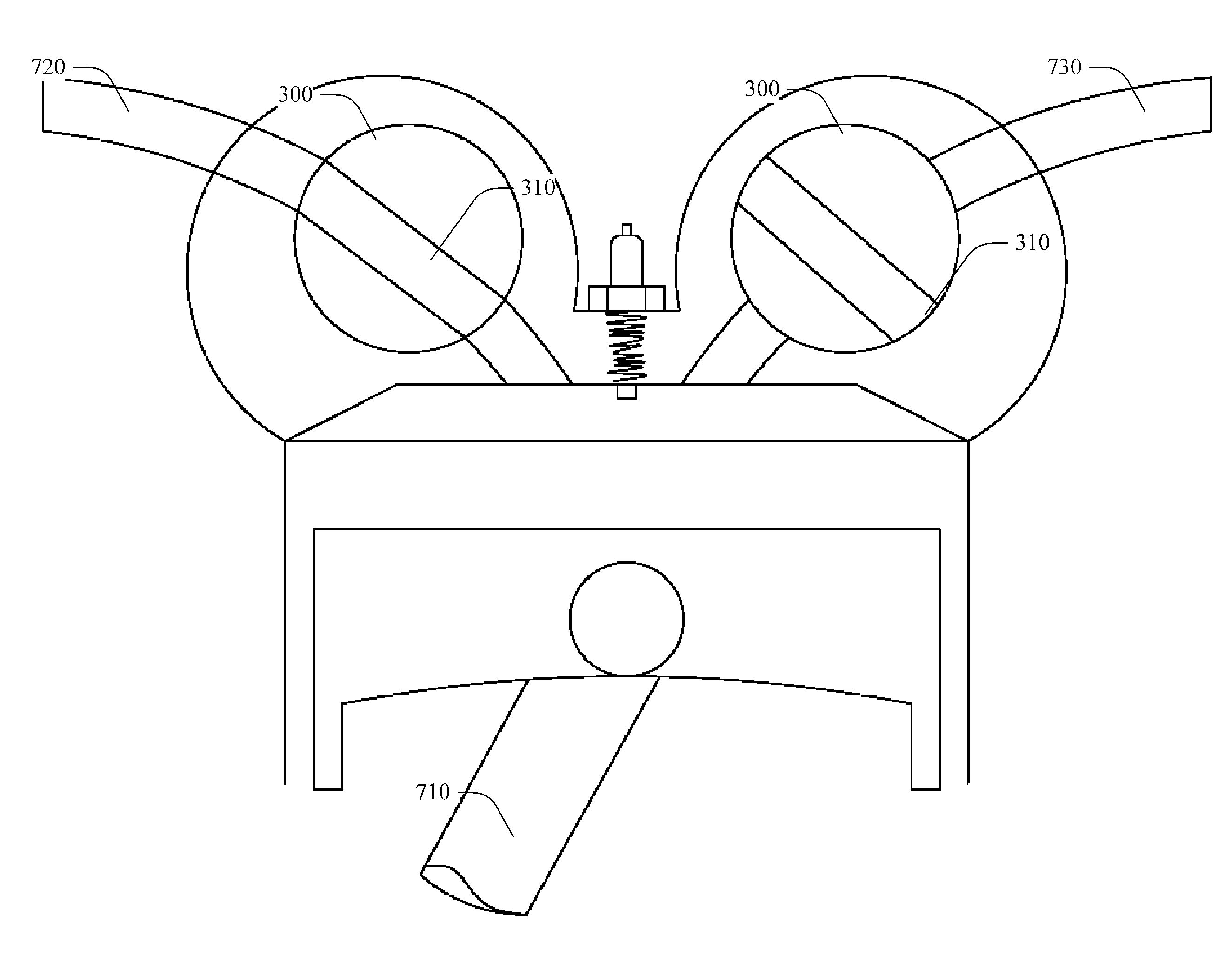
View PDF8 Cites 3 Cited by
  • Summary
  • Abstract
  • Description
  • Claims
  • Application Information

AI Technical Summary

Benefits of technology

[0004]Removing the camshaft and valves would improve the four-stroke engine through a reduction in moving parts and through improved airflow, which would translate to better fuel economy and horsepower gains. A rotating shaft, timed just right, with a cross-hole through it, or multiple cross-holes, would allow airflow in or out without having the restrictive nature associated with present day design.
[0005]One embodiment of an improved motor includes a rotating shaft(s) including a hole or multiple cross-holes aligned with (or over) the pistons to better facilitate airflow to and from the engine. The core of the engine further includes the block, intake, exhaust, serpentine belt, flywheel, bell housing, pistons, etc. Since the airflow in and out of the engine is more efficient, the engine itself is more efficient. Using the improved shaft with at least one hole aligned with the pistons, smaller engines would make the same power as larger engines without the improved shaft. Furthermore, through the use of the improved motor and the improved shaft, alternative fuels such as hydrogen or biomass derived fuels are more attractive fuels for powering a motor.
[0006]One skilled in the art will recognize appropriate metals and proper formation of cross-holes in light of this disclosure. Although metal is a common material used in the construction of engines, other materials are usable including, but not limited to: ceramics, plastics, etc. In one alternative, a proper seal is placed in the space or gap between the rotating shaft and shaft housing (head) to prevent intake or exhaust air from leaking.
[0007]The advantages of the improved engine include a reduction in hardware, improved airflow, improved fuel efficiency, fewer moving parts, and reduction in maintenance because, for example, carbon-build-up on valves is omitted.

Problems solved by technology

Valves are very restrictive to linear airflow, and airflow has to bend to get around the intake valve to get into the combustion chamber.
In addition to valves often being a weak component of the internal combustion engine, the bending of this airflow around the intake and exhaust valves creates inefficiencies.

Method used


Image

  • Internal combustion engine with modified shaft
  • Internal combustion engine with modified shaft
  • Internal combustion engine with modified shaft

Examples


Embodiment Construction

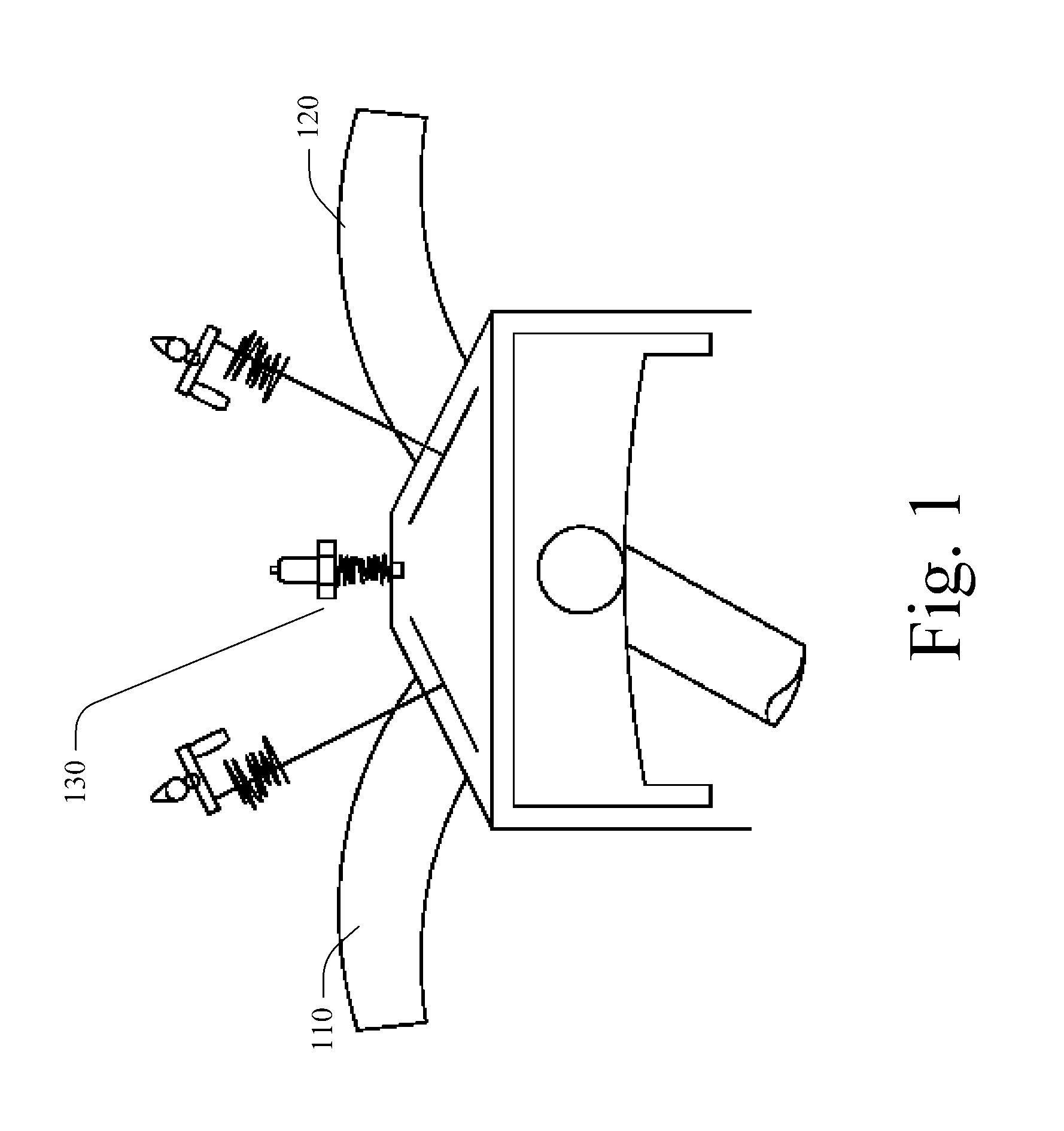
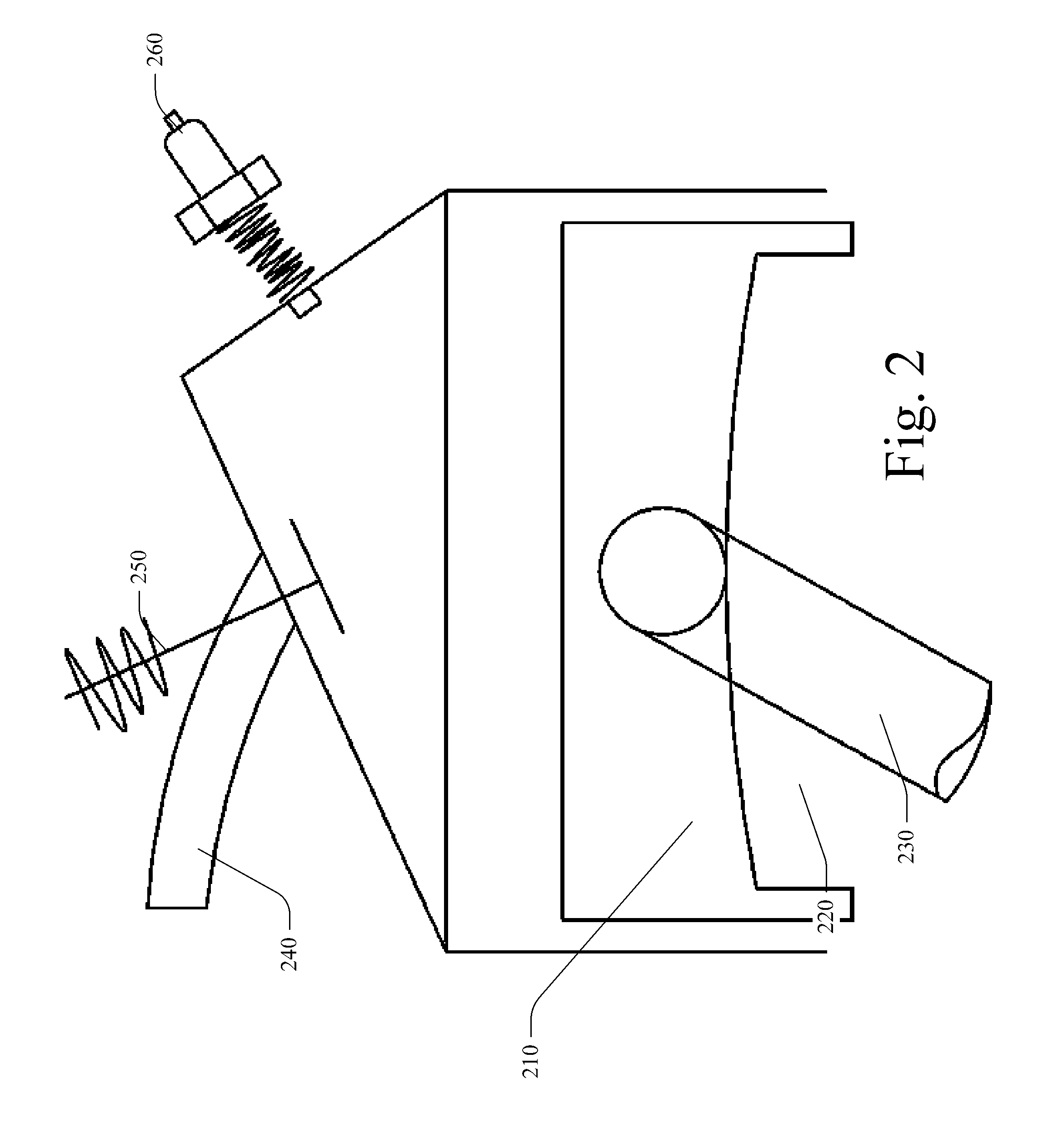
[0028]FIG. 1 depicts a typical piston cylinder arrangement for a single- or dual-overhead cam arrangement whereby the valves permit entry and exit of air. In this arrangement, the valves are integral to the operation of this four-stroke engine. For the four-stroke engine, the first stroke is the piston moving in a downward motion, and the intake valve 110 of FIG. 1 is open to permit air entry. On the upward stroke of the piston, the valves are closed. On the third stroke, the piston is moving in the downward direction and, at the same time, the valves are still closed. Near the bottom of the power stroke, the exhaust valve 120 opens, allowing spent gases to exit during the fourth (exhaust) stroke. Typical single- or dual-overhead cam arrangements show a hemispherical chamber, cylinder, piston, connecting rod, and valve arrangement whereby an intake valve (left) and exhaust valve (right) introduce air into the engine and permit the exit of combustion byproducts. In this design, the s...


PUM


Abstract

In one embodiment, an improvement to a four-stroke engine having a single cylinder block arrangement including an engine block, timing gears, crankshaft and gear, timing belt / chain, intake port, exhaust port, and cylinder head arrangement includes a ported rotating shaft, the ported rotating shaft having a first port, the ported rotating shaft synchronized with the crankshaft, such that the first port periodically aligns with the intake port to allow for intake during the four-stroke cycle.

Description

CROSS-REFERENCE TO RELATED APPLICATIONS[0001]This Application claims the benefit of U.S. Provisional Patent Application No. 61 / 308,841 filed on Feb. 26, 2010, which is hereby incorporated by reference.BACKGROUND[0002]The internal combustion engine has remained mostly unchanged for the past 100 years with most advancements emanating from improvements in fuel injection (e.g., direct fuel injection), variable valve timing, camshaft design, and emissions controls. However, every four-stroke engine manufactured in the past 100 years is pretty much the same configuration. They all use crankshafts, connecting rods, pistons, and rings in the block area. There are slight variations in the head and intake area, but most use camshafts, valves, valve springs, retainers, etc. Some use lifters, pushrods, and rocker arms, some use followers, and some use the camshaft pushing right over the valve with a “bucket” on top of the valve. However, they all use camshafts and valves.[0003]Valves are very r...

Claims


Application Information

Patent Timeline
Patent Type & Authority Applications(United States)
IPC IPC(8): F01L7/02F01L31/00
CPCF01L7/026F01L7/021
Inventor MYERS, RUSSELL S.
Owner MYERS RUSSELL S
Learn More