Composite mold, plastic working device for workpiece material, and plastic working method for workpiece material

a technology of working device and workpiece material, which is applied in the direction of extrusion die, drawing profiling tool, manufacturing tools, etc., can solve the problems of large dynamic frictional force between the workpiece material and the passage wall surface, large shearing force and accompanying severe strain on the workpiece material, and molds to be early worn or damaged, so as to reduce the grain size of the workpiece material, reduce the pressurizing force to be applied to the workpiece material, and reduce the grain

Active Publication Date: 2009-05-14
JTEKT CORP +2
View PDF0 Cites 0 Cited by
  • Summary
  • Abstract
  • Description
  • Claims
  • Application Information

AI Technical Summary

Benefits of technology

[0098]Also, according to the composite mold of the invention, most part of the relative movement force of the first mold and the second mold can be utilized as part of the force for reducing the grain size of the workpiece material. That is, according to the invention, the frictional force between the wall surface of the groove and the side faces of the workpiece material can be reduced to a large extent, unlike conventional molds in which frictional force between the wall surface of the groove and the side faces of the workpiece material makes the culprit of various problems. Therefore, the pressurizing force to be applied to the workpiece material can be reduced to a large extent, as compared with conventional molds which require pressurizing forces that overcome the frictional force between the workpiece material and the mold wall surface due to the force for pushing the workpiece material against the mold wall surface. Further, the force for reducing the grain size of the workpiece material can be greatly reduced from several hundreds of tons to several tons or less. Consequently, the sliding resistance in the through hole is so small that the life of the mold can be prolonged, and moreover the cost for plastic deformation of the workpiece material can be greatly reduced.
[0099]Further, according to the plastic working device for workpiece material in the invention, the first mold can be moved relative to the second mold by the first relative movement unit, and the workpiece material substantially immovably retained in the groove of the first mold can be bent by the first guide portion and pushed from the groove into the through hole. Therefore, a very large shearing force can be given to the workpiece material at around the first guide portion, so that the crystal grain size of the workpiece material can be micro-fined. Thus, material characteristics (strength, durability and the like of the material) after the working of the workpiece material can be greatly improved.
[0100]Also, according to the plastic working device for workpiece material in the invention, since the workpiece material is scarcely moved relative to the first mold, the first mold can be substantially completely prevented from occurrence of damage due to the movement relative to the workpiece material.
[0101]Also, according to the plastic working device for workpiece material in the invention, since the relatively moving part of the workpiece material can be reduced by an extent corresponding to the size of the groove so as to be restricted roughly only to the part of the through hole, and moreover parts on which large force acts can be restricted roughly to proximities to the first guide portion of the second mold as well as to the through hole. Accordingly, occurrence of damage of the first and second molds can be suppressed to a large extent, as compared with conventional molds in which the whole passage moves relative to the workpiece material, and the lives of the first and second molds can be greatly prolonged as compared with those of conventional molds.
[0102]Also, according to the plastic working method for workpiece material in the invention, since the workpiece material substantially immovably retained in the groove of the first mold is bent by the first guide portion and pushed from the groove into the through hole by moving the first mold relative to the second mold, the workpiece material is scarcely moved relative to the first mold, so that the first mold can be substantially completely prevented from occurrence of damage due to the movement relative to the workpiece material.
[0103]Also, according to the plastic working method for workpiece material in the invention, since parts on which large force acts can be restricted roughly to proximities to the first guide portion of the second mold as well as to the through hole, relatively moving part of the workpiece material can be reduced by an extent corresponding to the size of the groove so as to be restricted roughly only to the part of the through hole. Accordingly, occurrence of damage of the first and second molds can be suppressed to a large extent, as compared with conventional molds in which the whole passage moves relative to the workpiece material, and the lives of the first and second molds can be greatly prolonged as compared with those of conventional molds.

Problems solved by technology

During the passage of the workpiece material through the bent portion, the workpiece material is forcedly changed in its extending direction, thereby causing a severe shearing force and an accompanying severe strain to occur to the workpiece material in the passage of the workpiece material through the bent portion.
Unfortunately, with the conventional method described above, since the workpiece material is moved in the U-shaped passage by applying pressurizing force to the end face of the rod-like workpiece material having a cross-sectional shape generally identical to the cross-sectional shape of the U-shaped passage, the workpiece material is laterally strained in proportion to Poisson's ratio by the pressing force, i.e., the workpiece material is stretched perpendicularly to the extending direction of the workpiece material, so that a dynamic frictional force between the workpiece material and the passage wall surface becomes enormously large.
This causes the mold to be early worn or damaged, leading to a problem that the mold life is very short.
Also, because of the enormously large dynamic frictional force between the workpiece material and the passage wall surface as described above, the force required to move the workpiece material in the U-shaped passage becomes very large.
This causes a problem that an apparatus for plastically deforming the workpiece material or energy cost for driving the apparatus is very large.
However, with this method also, since the workpiece material is pressurized from its one end, the workpiece material is laterally strained, so that a dynamic frictional force between the workpiece material and the material passage becomes enormously large.
This causes such problems as the mold's shorter life and very high cost due to the large pressing force for the plastic deformation of the workpiece material.

Method used


Image

  • Composite mold, plastic working device for workpiece material, and plastic working method for workpiece material
  • Composite mold, plastic working device for workpiece material, and plastic working method for workpiece material
  • Composite mold, plastic working device for workpiece material, and plastic working method for workpiece material

Examples


first embodiment

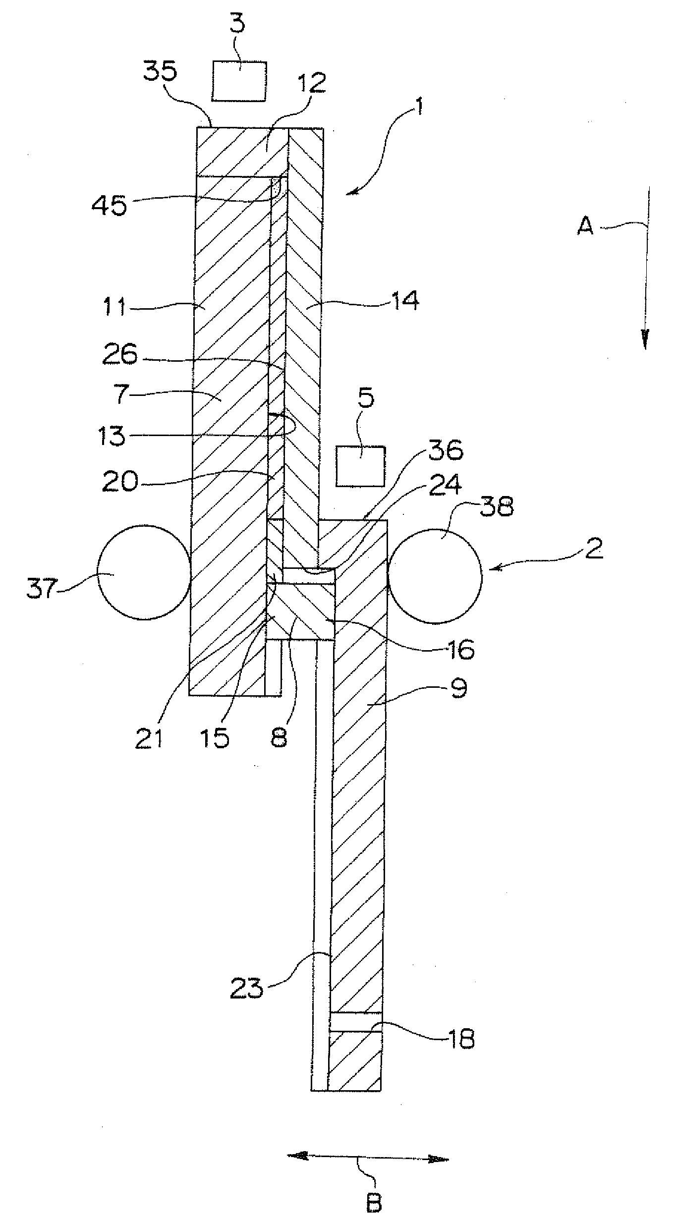
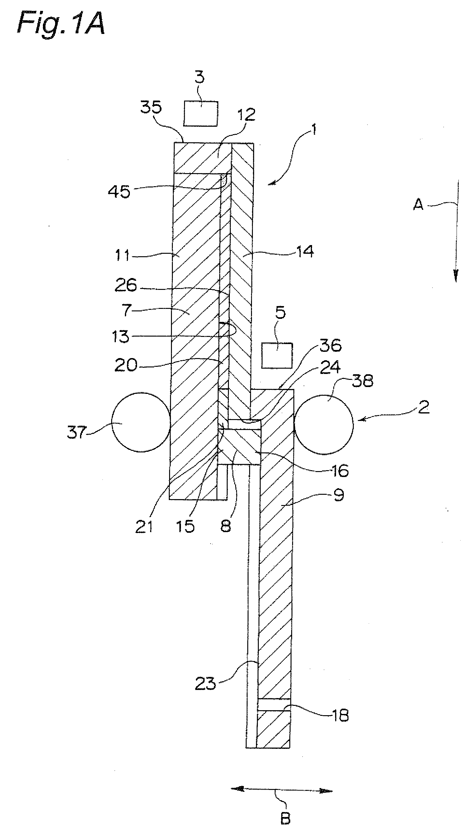
[0125]FIG. 1A is a sectional view of a plastic working device for workpiece material according to the invention (hereinafter, referred to as plastic working device). In FIG. 1A, reference numeral 20 denotes a titanium material made of pure titanium, which is an example of the workpiece material, and 21 denotes a dummy material serving for easier extrusion of the titanium material 20.

[0126]As shown in FIG. 1A, the plastic working device includes a composite mold 1 of the first embodiment of the invention, a retainer unit 2, a preloading press 3 as an example of a first relative movement unit, and a preloading press 5 as an example of a second relative movement unit. The composite mold 1 has a first mold 7, a second mold 8 and a third mold 9. The first mold 7, the second mold 8 and the third mold 9 are made of a mold metal.

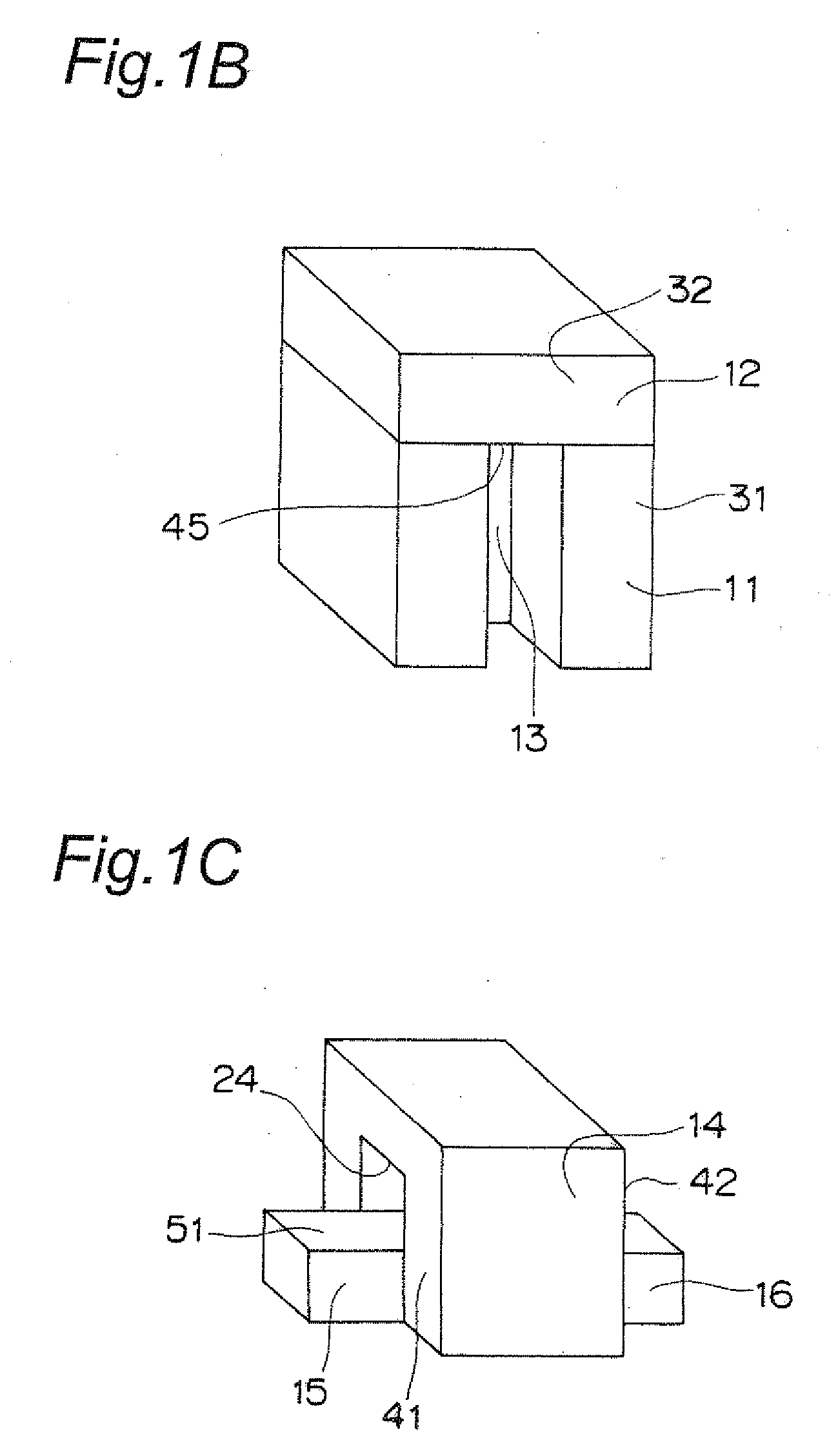
[0127]The first mold 7 has a body portion 11 and an end portion 12. The body portion 11 has a generally rectangular parallelepiped shape. At a roughly widthwise cen...

second embodiment

[0188]According to the composite mold of the second embodiment, the workpiece material retained by the groove 13 of the first mold 7 can be easily pushed into the groove 23 of the third mold 9 via the through hole 24 of the second mold 78, and conversely, the workpiece material retained by the groove of the third mold 9 can be easily pushed into the groove 13 of the first mold 7 via the through hole 24.

[0189]In addition, in the composite mold of the second embodiment, the side face portion 51 for bending the workpiece material in the first guide portion 15 of the first mold 7, and the first portion 84 in one side face of the through hole 24, are positioned so as to be generally flush with each other, and moreover the portion 81 of the side face of the second guide portion 86 and the second portion 85 generally perpendicular to the first portion 84 in the side face of the through hole 24 are positioned so as to be generally flush with each other. However, in the case where the cross-...

fourth embodiment

[0190]Also in the case where the cross-sectional shape of the through hole of the second mold is a generally rectangular shape, it is also allowable, as the composite mold of the invention, that the side face portion for bending the workpiece material in the first guide portion and the first portion in one side face of the through hole are positioned so as to be generally flush with each other while a portion of one side face of the second guide portion and the second portion of a side face of the through hole generally parallel to the first portion are positioned so as to be generally flush with each other.

[0191]FIG. 5A is a perspective view showing a shape of a workpiece material 91 which is being extruded from the groove 13 of the first mold 7 to the groove 23 of the third mold 9 in the composite mold 1 of the first embodiment. FIG. 5B is a perspective view showing a shape of a workpiece material 92 which is being extruded from the groove 13 of the first mold 7 to the groove 23 o...


PUM

PropertyMeasurementUnit
shapeaaaaaaaaaa
cross-sectional shapeaaaaaaaaaa
pressing forceaaaaaaaaaa

Abstract

After a rod-like titanium material 20 is accommodated in a generally linear-shaped groove 13 of a first mold 7, a first guide portion 15 of a second mold 8 is fitted to the groove 13. Thereafter, the first mold 7 is moved along an arrow A direction relative to the second mold 8 fixed to an anchor block, by which the titanium material 20 substantially immovably retained in the groove 13 of the first mold 7 is bent and pushed into a through hole 24 of the second mold 8 by the first guide portion 15, thus being plastically deformed.

Description

TECHNICAL FIELD[0001]The present invention relates to a composite mold, a plastic working device for workpiece material and a plastic working method for workpiece material for performing, for example, so-called ECAP (Equal Channel Angular Pressing) process or the like.BACKGROUND ART[0002]When a material is subjected to a severely large compressive force so as to be bent and resultantly plastically deformed (i.e. so-called ECAP process), the material is micro-fined in crystal grain size with its strength dramatically improved. With a material of pure titanium as an example, its crystal grain size can be subdivided to about one thousandth so that the strength is improved by leaps and bounds. In particular, the ECAP process allows strength improvement to be achieved without alloying, thus being valuable. For example, a pure metal such as the plastically deformed pure titanium may preferably be used as a material of artificial teeth for use in implant techniques because it scarcely harm...

Claims


Application Information

Patent Timeline
Patent Type & Authority Applications(United States)
IPC IPC(8): B21C23/00B21C25/02
CPCB21C23/001B21C25/08B21C23/01
Inventor UENO, HIROSHIHASHIMOTO, SATOSHIVINOGRADOV, ALEXEI
Owner JTEKT CORP
Why Eureka
Try Eureka