Restraint

a technology of a sleeve and a sleeve is applied in the field of sleeve, which can solve the problem of reducing the projected diameter of the apertur

Inactive Publication Date: 2005-12-06
S&S WORLDWIDE
View PDF21 Cites 28 Cited by
  • Summary
  • Abstract
  • Description
  • Claims
  • Application Information

AI Technical Summary

Benefits of technology

[0007]In its most basic form, the Restraint of the present invention is a lap retainer which includes a lap bar attached to a seco

Problems solved by technology

Then attempting to withdraw the rod causes the rod to pull the block and thereby either maintain or increase the

Method used


Image

  • Restraint
  • Restraint
  • Restraint

Examples


Embodiment Construction

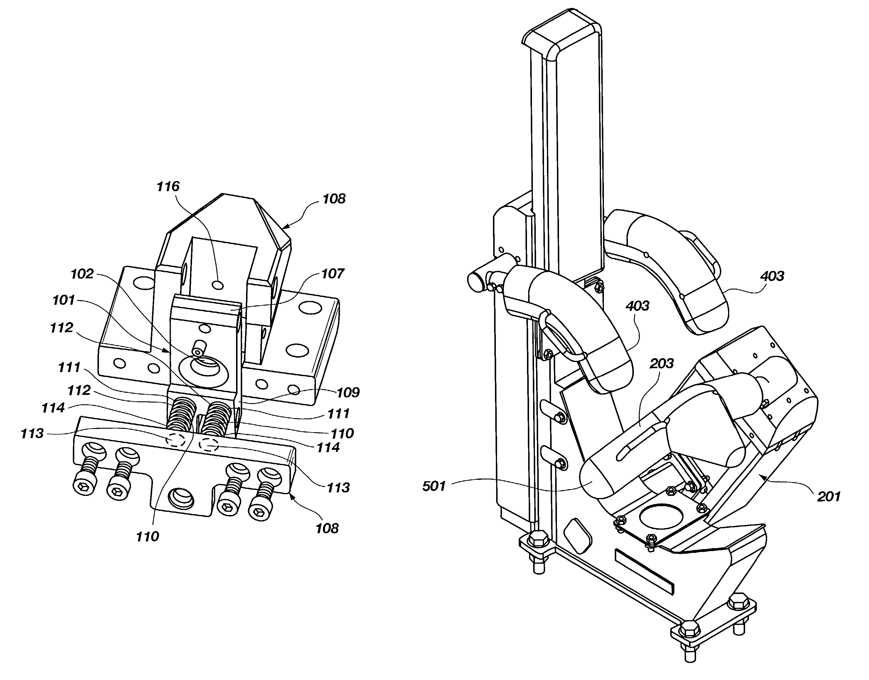
[0027]A key feature of the present Restraint is termed a rod lock 1. The rod lock 1 precludes longitudinal motion of a rod 103 either continuously or discretely along a portion of the rod 103.

[0028]A preferred version of the rod lock 1 is termed the “locking apparatus.”

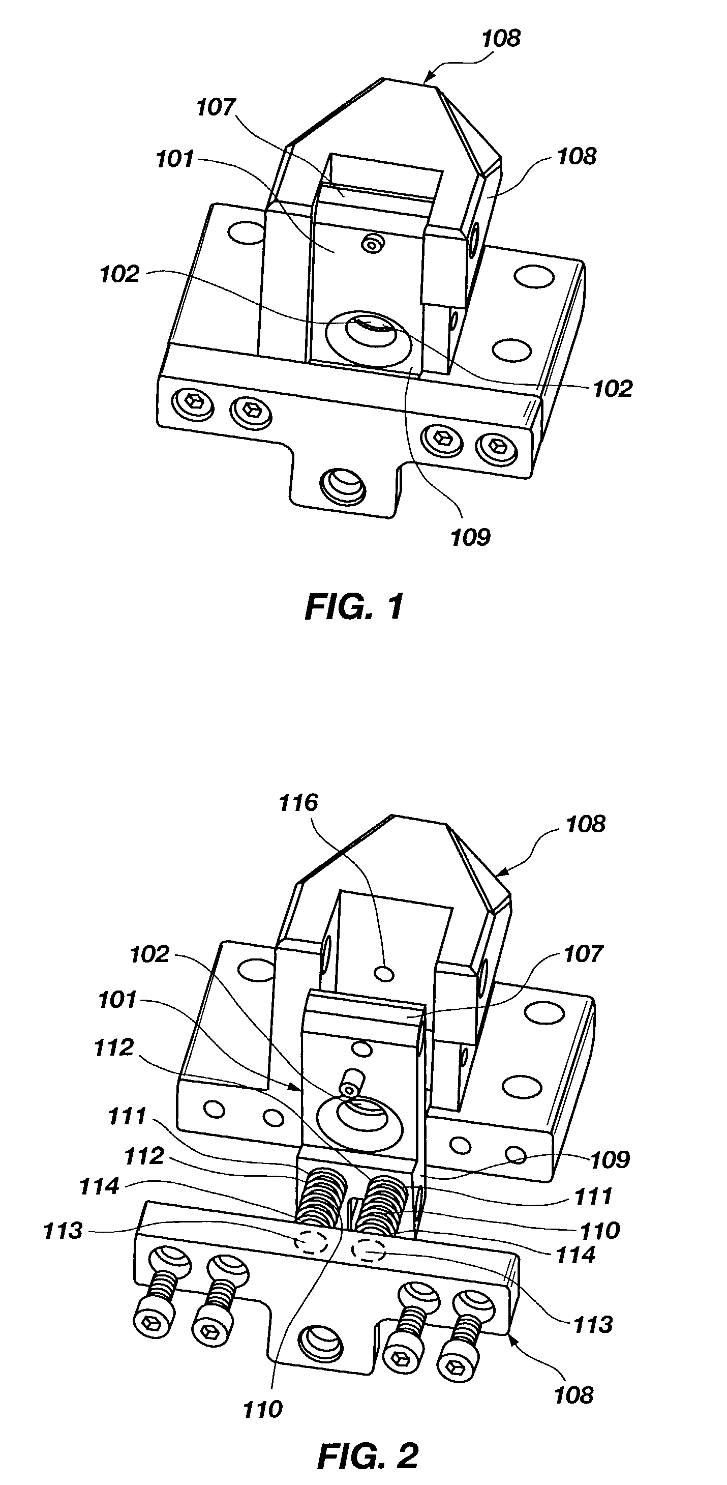
[0029]The locking apparatus has a block 101 containing an aperture 102.

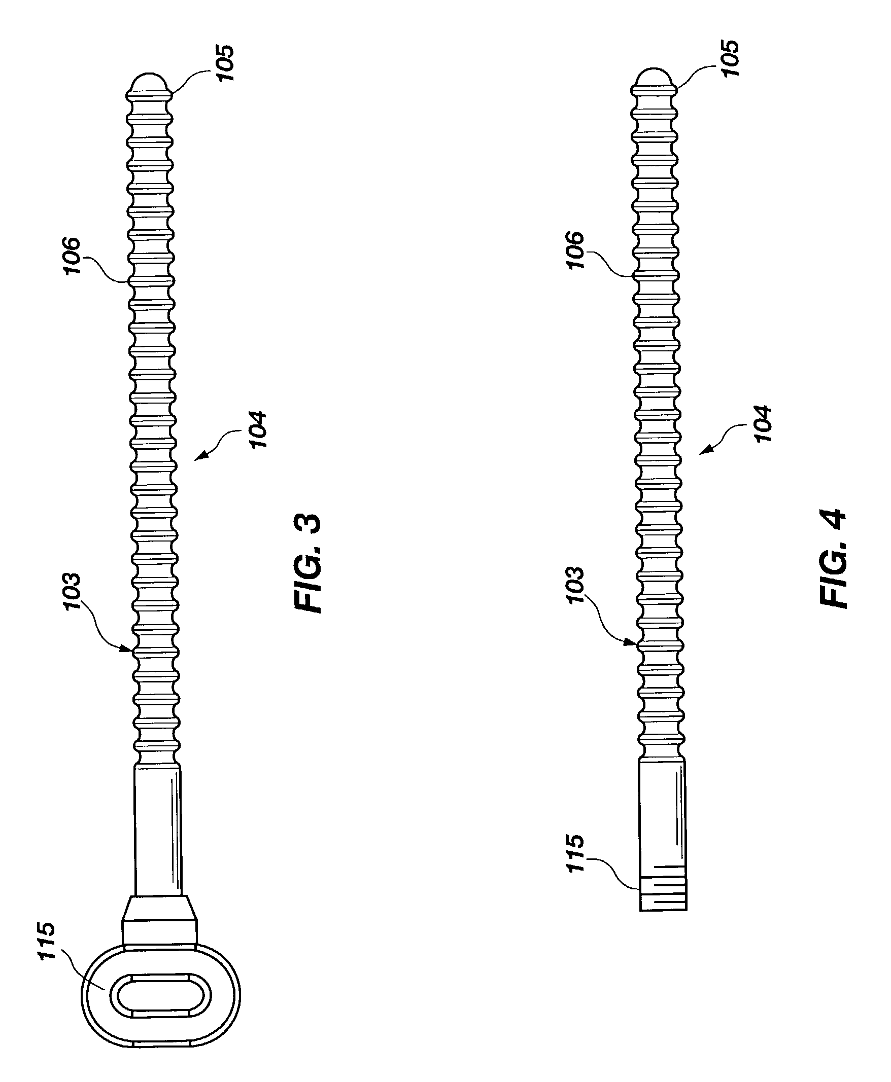
[0030]A rod 103 is removably insertable into the aperture 102. The rod 103 employed with the locking apparatus is serrated, i.e., the thickness of the rod 103 varies periodically along a portion 104 of the length of the rod 103 beginning near a first end 105 of the rod 103.

[0031]The maximum periodic thickness 106 of the rod 103 is less than the minimum diameter of the aperture 102 in the block 101 so that the rod 101 can be inserted into the aperture 102.

[0032]Between the center of the aperture 102 and a first end 107 of the block 101, the block is rotatably attached to a support structure 108. The block 101 is biased so that the second end 109 of ...


PUM


Abstract

A restraint for retaining a person within a seat. The restraint has a lap bar and a shoulder bar which can be independently adjusted. The lap bar can be rotated either to retain a person or to permit a person to enter or exit. Also, the lap bar can be pulled farther away or pushed closer to a person. When extended completely, the lap bar will remain locked in such position until the lap bar is rotated toward the position a person will occupy. When pushed toward a person, the lap bar cannot be pushed farther away until a rod to which the lap bar is attached is released from a lock. The shoulder retainer is attached to a similar rod which is locked in this same fashion.

Description

BACKGROUND OF THE INVENTION[0001]1. Field of the Invention[0002]This invention relates to a restraint for retaining a person within a seat.[0003]2. Description of the Related Art[0004]The Inventor is aware of no other rigid restraint employing a rod lock as described in this invention for the lap of a person within a seat and is also aware of no rigid restraint which can be adapted both to the height and lap size of a participant.[0005]A hydraulic lock such as the one discussed below was employed on amusement rides by S & S Sports Power, Inc. of Logan, Utah, that was available to the public on or shortly after Oct. 18, 1994.[0006]A locking apparatus similar to the one considered below was employed on amusement rides by S & S Sports Power, Inc. of Logan, Utah, on or shortly after Aug. 4, 2001, and is the subject of copending U.S. application Ser. No. 09 / 922,588, filed on Aug. 3, 2001.SUMMARY OF THE INVENTION[0007]In its most basic form, the Restraint of the present invention is a lap...

Claims


Application Information

Patent Timeline
IPC IPC(8): B60R21/00B60R21/02
CPCB60R21/02B60R2021/0058Y10T24/45602B60R2021/022B60R2021/0097
Inventor HANSEN, NED R.CHECKETTS, QUIN R.WILKINSON, S. RHODES
Owner S&S WORLDWIDE
Why Eureka
Try Eureka