Variable cycle engine and operation mode switching method

a technology of operation mode and variable cycle engine, which is applied in the direction of electrical control, non-mechanical valves, ignition automatic control, etc., can solve problems such as difficulty in smooth switching of modes

Inactive Publication Date: 2005-12-06
TOYOTA JIDOSHA KK
View PDF23 Cites 28 Cited by
  • Summary
  • Abstract
  • Description
  • Claims
  • Application Information

AI Technical Summary

Benefits of technology

[0011]It is an object of the invention to provide an internal combustion engine having a plurality of operation modes which allows a smooth switching of the operation mode.

Problems solved by technology

In the internal combustion engine of the aforementioned type, however, there has been a difficulty in a smooth switching of the mode between the spark ignition mode operation and the self-ignition mode operation.

Method used


Image

  • Variable cycle engine and operation mode switching method
  • Variable cycle engine and operation mode switching method
  • Variable cycle engine and operation mode switching method

Examples


first embodiment

A.

[0057]A-1. Structure:[0058]A-2. Operation in the operation mode in accordance with operation area:[0059]A-3. Valve operation timing in each operation mode:[0060]A-4. Transition from 4-cycle mode under spark ignition control to 2-cycle mode under self ignition control:[0061]A-5. Transition from 2-cycle mode under self ignition control to 4-cycle mode under spark ignition control:

B. Second Embodiment:[0062]B-1. Transition from 2-cycle mode under self ignition control to 4-cycle mode under self ignition control:[0063]B-2. Transition from 4-cycle mode under self ignition control to 2-cycle mode under self ignition control:

C. Third Embodiment:[0064]C-1. Transition from 4-cycle mode under spark ignition control to 4-cycle mode under self ignition control:[0065]C-2. Transition from 4-cycle mode under self ignition control to 4-cycle mode under spark ignition control:

D. Fourth Embodiment:[0066]D-1. Transition from 4-cycle mode under spark ignition control to 2-cycle mode under self igniti...

second embodiment

B. Second Embodiment

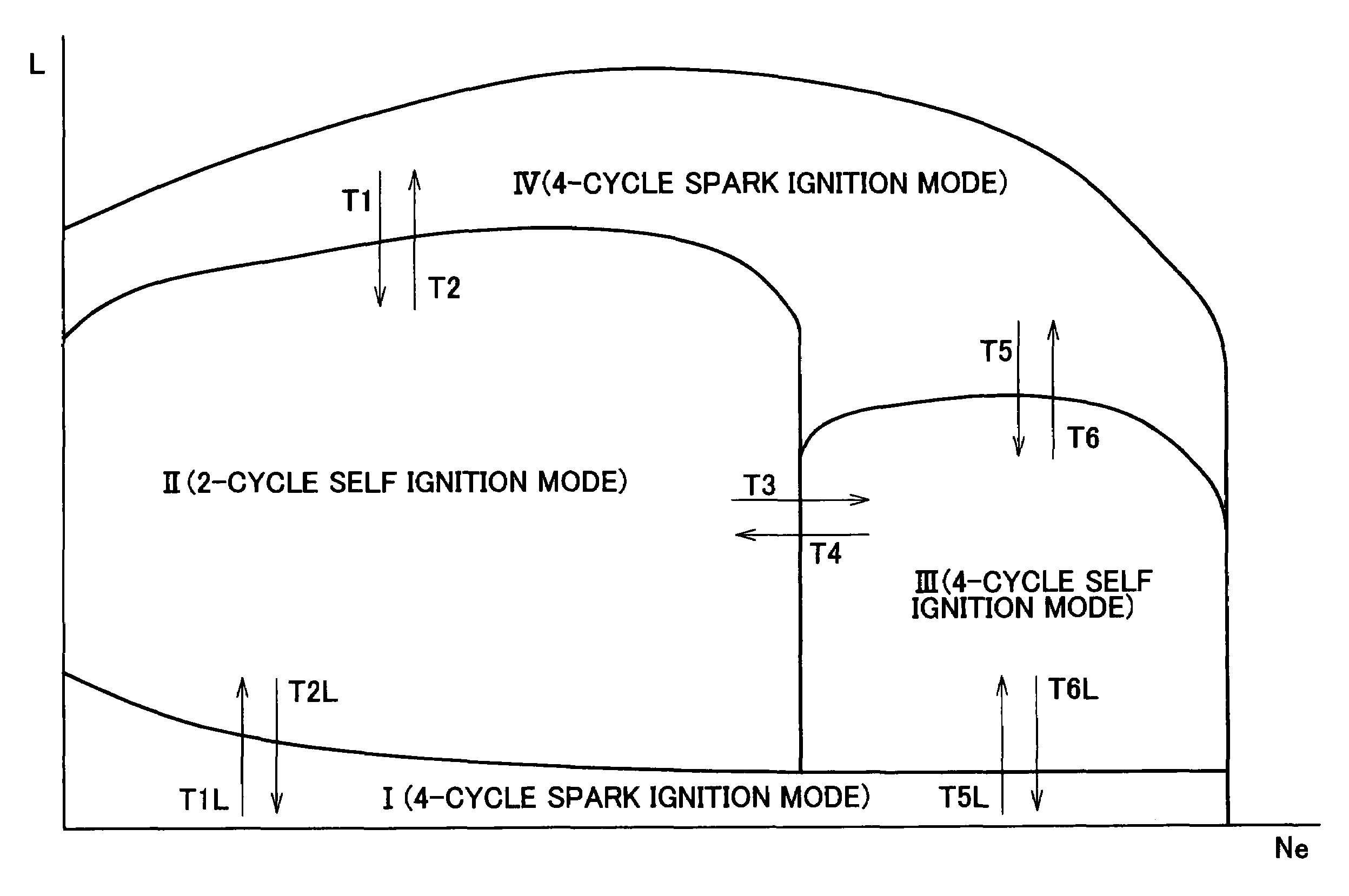
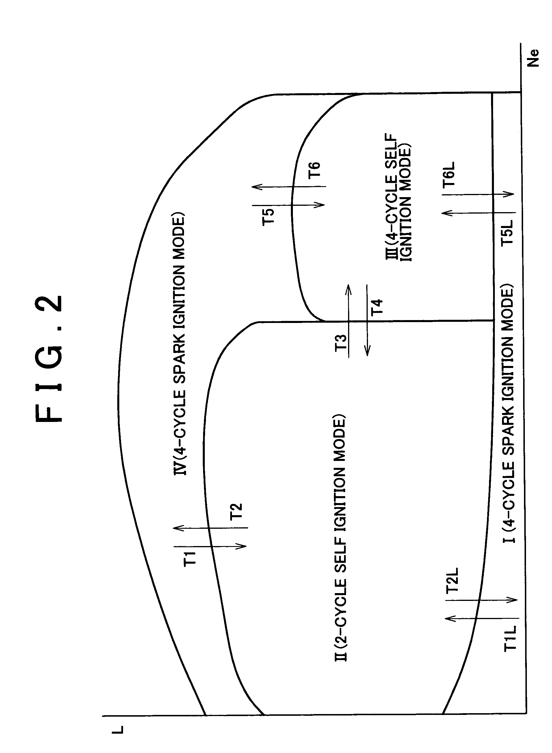
[0137]In a second embodiment, switching of the operation mode between 2-cycle mode under self ignition control in the medium load at low engine speed and 4-cycle mode under self ignition control in the medium load at high engine speed will be described. The transition from 2-cycle mode under self ignition control to 4-cycle mode under self ignition control is represented by an arrow T3 as shown in FIG. 2. The transition from 4-cycle mode under self ignition control to 2-cycle mode self ignition control is represented by an arrow T4 as shown in FIG. 2. The structure of the engine 10, each operation of the respective modes and the like are the same as those described in the first embodiment.

B-1 Transition from 2-Cycle Mode under Self Ignition Control to 4-Cycle Mode under Self Ignition Control

[0138]FIG. 9 is a view that shows timing for operating both the intake valve 132 and the exhaust valve 134 in the transition cycle T3 upon transition from 2-cycle mode under s...

third embodiment

C. Third Embodiment

[0153]In a third embodiment, switching of the operation mode between 4-cycle mode under spark ignition control in the high load and 4-cycle mode under self ignition control will be described. The transition from the 4-cycle mode under spark ignition control in the high load to the 4-cycle mode under self ignition control is represented by arrow T5. The transition from the 4-cycle mode under self ignition control to the 4-cycle mode under spark ignition control in the high load is represented by arrow T6 . The structure of the engine 10 and each operation of the respective modes are the same as those described in the first embodiment.

C-1. Transition from 4-Cycle Mode under Spark Ignition Control to 4-Cycle Mode under Self Ignition Control

[0154]FIG. 10 is a view that represents the timing for operating the intake valve 132 and the exhaust valve 134 in a transition cycle T5 performed upon transition of the operation mode from 4-cycle mode under spark ignition control...


PUM


Abstract

An engine is operated in accordance with a plurality of operation modes obtained by combining one of a 4-cycle mode and a 2-cycle mode with one of a combustion ignition control where an ignition is performed with an ignition unit and a self ignition priority control including the ignition performed without the ignition unit. Upon switching of the operation mode, a transition cycle is performed once between a first operation mode before switching of the operation mode and a second operation mode after switching of the operation mode. Timing for operating an intake valve or an exhaust valve in the transition cycle is different from that in the second operation mode. The combustion ignition control is executed in one of the combustion chambers where the single operation of the transition cycle is completed until a single cycle of each transient cycle in the rest of the combustion chambers is terminated.

Description

INCORPORATION BY REFERENCE[0001]The disclosure of Japanese Patent Application No. 2003-055605 filed on Mar. 3, 2003, including the specification, drawings and abstract are incorporated herein by reference in its entirety.BACKGROUND OF THE INVENTION[0002]1. Field of Invention[0003]The invention relates to a variable cycle engine that is switchable between a 4-cycle mode and a 2-cycle mode, and more particularly to a technology that is capable of switching the operation of the variable cycle engine smoothly between the 4-cycle mode and the 2-cycle mode.[0004]2. Description of Related Art[0005]An internal combustion engine having two operation modes, that is, a spark ignition mode where the fuel is combusted with spark ignition, and a self-ignition mode where the fuel is combusted with compressed self-ignition has been known as being disclosed in JP-A-11-280504 and other publications as listed below;[0006]JP-A-11-336647,[0007]JP-A-2000-192828,[0008]JP-A-2001-152919, and[0009]JP-A-10-10...

Claims


Application Information

Patent Timeline
Patent Type & Authority Patents(United States)
IPC IPC(8): F02B1/04F02B1/12F02B11/00F02B69/06F02B75/02F02B75/18F02B75/20F02D13/02F02D41/04F02D41/30F02D41/36F02D43/00F02D45/00F02P5/15
CPCF02B1/04F02B1/12F02B69/06F02B75/20F02D41/3058F02D41/307F02B2075/025F02B2075/027F02B2075/1812F02D41/3035
Inventor KOBAYASHI, TATSUOKATSUMATA, SHOUJI
Owner TOYOTA JIDOSHA KK
Why Eureka
Try Eureka